|
|
|
| Introduction | |
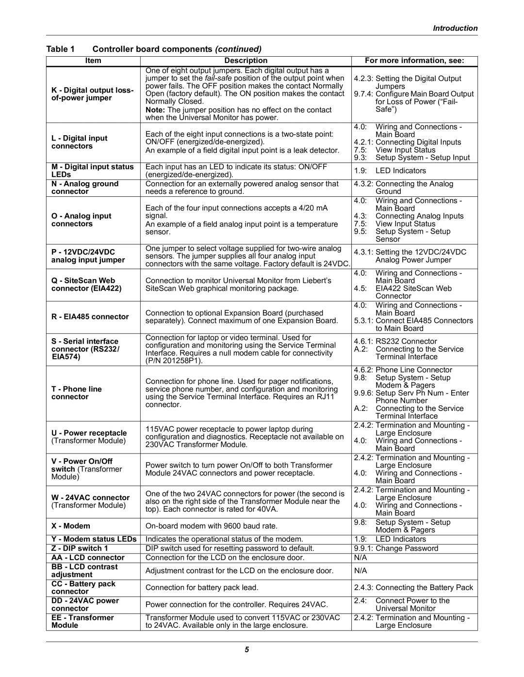
Table 1 | Controller board components (continued) |
|
| ||
|
|
| |||
Item | Description | For more information, see: | |||
|
| One of eight output jumpers. Each digital output has a | 4.2.3: Setting the Digital Output | ||
|
| jumper to set the | |||
K - Digital output loss- | power fails. The OFF position makes the contact Normally |
| Jumpers | ||
Open (factory default). The ON position makes the contact | 9.7.4: Configure Main Board Output | ||||
| |||||
Normally Closed. |
| for Loss of Power (“Fail- | |||
|
| Note: The jumper position has no effect on the contact |
| Safe”) | |
|
| when the Universal Monitor has power. |
|
| |
|
| Each of the eight input connections is a | 4.0: | Wiring and Connections - | |
L - Digital input |
| Main Board | |||
ON/OFF | 4.2.1: Connecting Digital Inputs | ||||
connectors | |||||
An example of a field digital input point is a leak detector. | 7.5: | View Input Status | |||
|
| ||||
|
|
| 9.3: | Setup System - Setup Input | |
M - Digital input status | Each input has an LED to indicate its status: ON/OFF | 1.9: | LED Indicators | ||
LEDs |
| ||||
|
|
| |||
N - Analog ground | Connection for an externally powered analog sensor that | 4.3.2: Connecting the Analog | |||
connector |
| needs a reference to ground. |
| Ground | |
|
| Each of the four input connections accepts a 4/20 mA | 4.0: | Wiring and Connections - | |
O - Analog input | 4.3: | Main Board | |||
signal. | Connecting Analog Inputs | ||||
connectors | An example of a field analog input point is a temperature | 7.5: | View Input Status | ||
|
| sensor. | 9.5: | Setup System - Setup | |
|
|
|
| Sensor | |
P - 12VDC/24VDC | One jumper to select voltage supplied for | 4.3.1: Setting the 12VDC/24VDC | |||
sensors. The jumper supplies all four analog input | |||||
analog input jumper |
| Analog Power Jumper | |||
connectors with the same voltage. Factory default is 24VDC. |
| ||||
|
|
|
| ||
Q - SiteScan Web | Connection to monitor Universal Monitor from Liebert’s | 4.0: | Wiring and Connections - | ||
4.5: | Main Board | ||||
connector (EIA422) | SiteScan Web graphical monitoring package. | EIA422 SiteScan Web | |||
|
|
|
| Connector | |
|
| Connection to optional Expansion Board (purchased | 4.0: | Wiring and Connections - | |
R - EIA485 connector |
| Main Board | |||
separately). Connect maximum of one Expansion Board. | 5.3.1: Connect EIA485 Connectors | ||||
|
| ||||
|
|
|
| to Main Board | |
S - Serial interface | Connection for laptop or video terminal. Used for | 4.6.1: RS232 Connector | |||
configuration and monitoring using the Service Terminal | |||||
connector (RS232/ | A.2: | Connecting to the Service | |||
Interface. Requires a null modem cable for connectivity | |||||
EIA574) |
|
| Terminal Interface | ||
| (P/N 201258P1). |
| |||
|
|
|
| ||
|
|
| 4.6.2: Phone Line Connector | ||
|
| Connection for phone line. Used for pager notifications, | 9.8: | Setup System - Setup | |
|
|
| Modem & Pagers | ||
T - Phone line | service phone number, and configuration and monitoring |
| |||
9.9.6: Setup Serv Ph Num - Enter | |||||
connector |
| using the Service Terminal Interface. Requires an RJ11 | |||
|
| Phone Number | |||
|
| connector. |
| ||
|
| A.2: | Connecting to the Service | ||
|
|
| |||
|
|
|
| Terminal Interface | |
|
| 115VAC power receptacle to power laptop during | 2.4.2: Termination and Mounting - | ||
U - Power receptacle |
| Large Enclosure | |||
configuration and diagnostics. Receptacle not available on |
| ||||
(Transformer Module) | 4.0: | Wiring and Connections - | |||
230VAC Transformer Module. | |||||
|
|
| Main Board | ||
|
|
|
| ||
V - Power On/Off |
| 2.4.2: Termination and Mounting - | |||
Power switch to turn power On/Off to both Transformer |
| Large Enclosure | |||
switch (Transformer |
| ||||
Module 24VAC connectors and power receptacle. | 4.0: | Wiring and Connections - | |||
Module) |
| ||||
|
|
| Main Board | ||
|
|
|
| ||
|
| One of the two 24VAC connectors for power (the second is | 2.4.2: Termination and Mounting - | ||
W - 24VAC connector |
| Large Enclosure | |||
also on the right side of the Transformer Module near the |
| ||||
(Transformer Module) | 4.0: | Wiring and Connections - | |||
top). Each connector is rated for 40VA. | |||||
|
|
| Main Board | ||
|
|
|
| ||
X - Modem |
| 9.8: | Setup System - Setup | ||
|
| Modem & Pagers | |||
|
|
|
| ||
Y - Modem status LEDs | Indicates the operational status of the modem. | 1.9: | LED Indicators | ||
Z - DIP switch 1 | DIP switch used for resetting password to default. | 9.9.1: Change Password | |||
AA - LCD connector | Connection for the LCD on the enclosure door. | N/A |
| ||
BB - LCD contrast | Adjustment contrast for the LCD on the enclosure door. | N/A |
| ||
adjustment |
|
| |||
|
|
|
| ||
CC - Battery pack | Connection for battery pack lead. | 2.4.3: Connecting the Battery Pack | |||
connector |
| ||||
|
|
|
| ||
DD - 24VAC power | Power connection for the controller. Requires 24VAC. | 2.4: | Connect Power to the | ||
connector |
|
| Universal Monitor | ||
|
|
| |||
EE - Transformer | Transformer Module used to convert 115VAC or 230VAC | 2.4.2: Termination and Mounting - | |||
Module |
| to 24VAC. Available only in the large enclosure. |
| Large Enclosure | |
5