Wiring and Connections - Main Board
4.2Connecting Digital Inputs and Digital Outputs
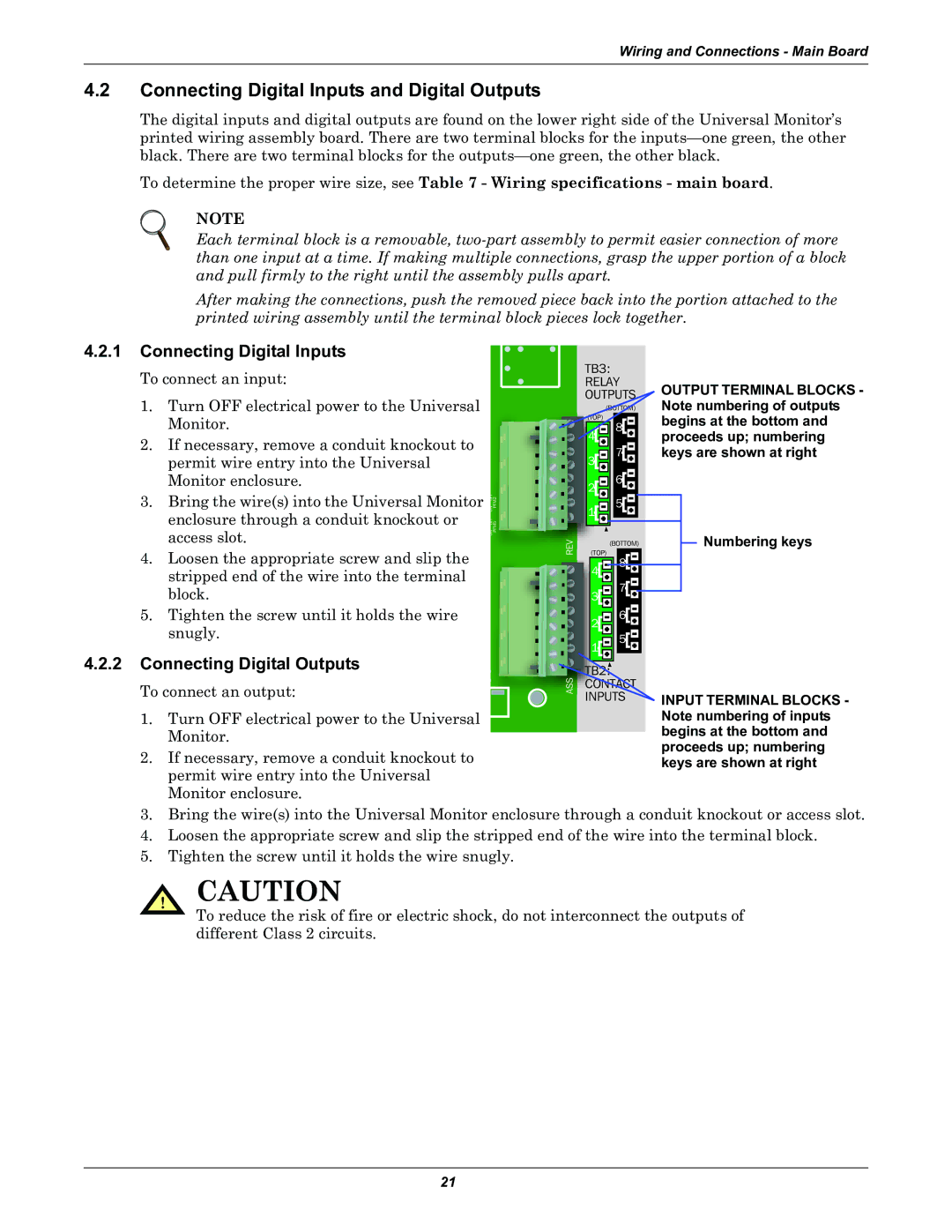
The digital inputs and digital outputs are found on the lower right side of the Universal Monitor’s printed wiring assembly board. There are two terminal blocks for the
To determine the proper wire size, see Table 7 - Wiring specifications - main board.
NOTE
Each terminal block is a removable,
After making the connections, push the removed piece back into the portion attached to the printed wiring assembly until the terminal block pieces lock together.
4.2.1 Connecting Digital Inputs
To connect an input:
1. | Turn OFF electrical power to the Universal |
|
|
| Monitor. |
|
|
2. | If necessary, remove a conduit knockout to |
|
|
| permit wire entry into the Universal |
|
|
| Monitor enclosure. |
|
|
3. | Bring the wire(s) into the Universal Monitor | ON OFF | PFM2 |
| enclosure through a conduit knockout or | ||
| ON OFF | PFM5 | |
| access slot. | ||
|
|
| |
4. | Loosen the appropriate screw and slip the |
|
|
| stripped end of the wire into the terminal |
|
|
| block. |
|
|
5. | Tighten the screw until it holds the wire |
|
|
| snugly. |
|
|
4.2.2 Connecting Digital Outputs
To connect an output:
1. Turn OFF electrical power to the Universal Monitor.
2. If necessary, remove a conduit knockout to permit wire entry into the Universal Monitor enclosure.
REV
ASS
TB3: |
|
|
| |||||||
RELAY | OUTPUT TERMINAL BLOCKS - | |||||||||
|
|
|
|
|
|
|
| |||
|
|
|
|
|
|
|
| Note numbering of outputs | ||
|
|
|
| 8 |
|
| begins at the bottom and | |||
|
|
|
|
|
|
|
| proceeds up; numbering | ||
3 |
|
| 7 |
|
| keys are shown at right | ||||
|
|
|
| |||||||
2 |
|
| 6 |
|
|
|
|
| ||
|
|
|
|
|
|
| ||||
1 |
|
| 5 |
|
|
|
| Numbering keys | ||
|
|
|
|
|
|
|
|
|
| |
|
|
|
|
|
|
|
|
|
| |
|
|
| (BOTTOM) |
|
| |||||
|
|
|
|
|
| |||||
| (TOP) |
|
|
|
|
|
| |||
| 8 |
|
|
|
|
| ||||
| 4 |
|
|
|
|
|
|
|
| |
|
|
|
|
|
|
|
|
| ||
|
|
|
| 7 |
|
|
|
|
| |
|
|
|
|
|
|
|
|
|
| |
| 3 |
|
|
|
|
|
|
|
| |
|
|
|
|
| 6 |
|
|
|
|
|
| 2 |
|
|
|
|
|
|
|
| |
|
|
|
|
| 5 |
|
|
|
|
|
| 1 |
|
|
|
|
| INPUT TERMINAL BLOCKS - | |||
|
|
|
|
|
|
|
| |||
INPUTS | ||||||||||
|
|
|
|
|
|
|
| Note numbering of inputs | ||
|
|
|
|
|
|
|
| begins at the bottom and | ||
proceeds up; numbering keys are shown at right
3.Bring the wire(s) into the Universal Monitor enclosure through a conduit knockout or access slot.
4.Loosen the appropriate screw and slip the stripped end of the wire into the terminal block.
5.Tighten the screw until it holds the wire snugly.
! CAUTION
To reduce the risk of fire or electric shock, do not interconnect the outputs of different Class 2 circuits.
21