Monitoring
Universal Monitor
Page
Table of Contents
Opening Screen Overview Main Menu Overview LCD Menu Overview
Setup System Setup I/O Matrix
Appendix B Default Settings Quick Reference Guide
Appendix a Service Terminal Interface
Figures
Page
Optional Features
Methods of Viewing and Configuring the Universal Monitor
Available Alarms
Data Logs
Outside Enclosure Overview
Enclosure has knockouts Access slots
On top
Transformer Module Back of LCD Controller Board
Universal Monitor Main board RS232 Phone Line
Typical Configuration
Digital outputs
Digital inputs
Controller board components
Controller Board Overview
Connector EIA422
Of-power jumper
EIA485 connector
Connector RS232
Expansion board components
Optional Expansion Board Overview
LED indicators summary
LED Indicators
Color Description Power status
LED Indicators Optional Expansion Board
EIA485 status LEDs D4 yellow D5 red
General status LED D3 green
Typical Sequence
Installation Main Board
Installation Considerations
Packing Contents
Unpacking and Preliminary Inspection
Required tools
Surface-Mounting the Universal Monitor
Mounting the Panel
Bottom hole diameter
Flush-Mounting the Universal Monitor
Input Power Connections Small Enclosure
Connect Power to the Universal Monitor
VAC Output Power Connections
Input Power Connections
Termination and Mounting Large Enclosure
Connection Type
Connecting the Battery Pack
Troubleshooting Transformer Module
Obtaining a Replacement Battery Pack
Problem Possible Solution Replacement Fuse Part Numbers
Packing manifest optional Expansion Board
Installation Optional Expansion Board
Surface-Mounting the Optional Expansion Board
Mounting Dimensions optional Expansion Board
Flush-Mounting the Optional Expansion Board
Pre-wired
Input Power Connections Optional Expansion Board
24VAC wiring red & white 24VAC input connectors AC1 & AC2
TM115 shown
Wiring Specifications
Wiring and Connections Main Board
Wiring specifications main board
Connecting Digital Inputs
Connecting Digital Inputs and Digital Outputs
Connecting Digital Outputs
Proceeds up numbering keys are shown at right
Connecting Analog Inputs
Setting the Digital Output Jumpers
Digital output jumper settings
Connecting the Analog Ground
Setting the 12VDC/24VDC Analog Power Jumper
EIA422 SiteScan Web Connector
Connecting Common Alarm Outputs
1 RS232 Connector
Phone Line Connector
Wiring specifications optional Expansion Board
Wiring and Connections Optional Expansion Board
Numbering keys
Connecting Inputs and Outputs
Relay is Closed On power failure
Numbering
Keys
Setting the Digital Output DIP Switches
DIP switch setting outputs wired as Normally Closed N.C
DIP switch setting outputs wired as Normally Open N.O
Connect EIA485 Connectors to Main Board
Enable the Connection via Firmware
Connect to the Universal Monitor
Guide to Universal Monitor functions
Overview of Menus
Opening Screen Overview
Main Menu Overview
LCD Menu Overview
View Status Options
Active Alarms
View Active Alarms
Clearing Active Alarms
Active Alarms
Alarm Log
View Alarm Log
Alarm log conditions Main Menu
Alarm Log
Event Log
View Event Log
Event Log
Event log conditions
View Trend Log
Select a Sensor
View a Trend Log
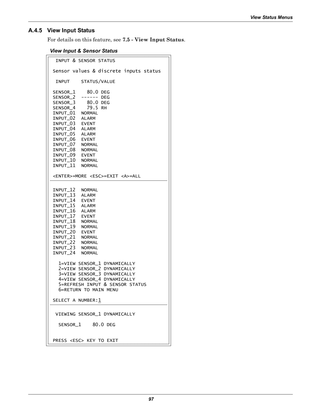
View Input Status
Input Status
Viewing Additional Input Data
Output Status
View Output Status
Viewing Additional Output Data
Digital output states
Select a Pager
View Pager Numbers
View a Pager Number
View a Pager PIN
Silence Alarm Service Terminal Interface only
Silence Alarm & Backup LOG Files Service Terminal Interface
Back Up Log Files Service Terminal Interface only
Silence Alarm & Backup Log Files Service Terminal Interface
Login
Login
System and Control Options
Valid characters for data entry
System & Control menu Setup System selected
Login Screen
Setup System menu
System & Control menu Clear Alarms&Logs selected
Setup System Setup Input
Setup System Overview
Define Input as Alarmable or Event
Change Label Name of Input
Define Input as Normally Open or Normally Closed
Set Up Delay Time
Set Up Alarmable Inputs in Latched or Unlatched Mode
Delay Time
Latched / Unlatched
Change to Reset Y or Not Reset N
Setup System Setup Common Alarm
Reset Common Alarm
Setup Common Alarm Setup Sensor
Setup System Setup Sensor
Select a Sensor to Configure
Default settings analog sensor inputs
Identify the Sensor as Connected
Change Sensor Label Name
Change Units Label
Change 4 mA Value
Change 20 mA Value
Change Offset Value
Define Sensor as Alarmable or Event
Set Up Alarmable Sensors in Latched or Unlatched Mode
Message if sensor has been defined as an event
Change High Setpoint
Change Low Setpoint
Change Low Setpoint
Change High Setpoint
Sensor Delay
Setup System Setup I/O Matrix
Set Up Mapping for a Digital Input
Map Input to a Main Board Output
Default mapping of digital inputs to digital outputs
Default Mappings Digital Inputs to Outputs
Digital input By default, mapped to digital output
Map Input to Expansion Board Output
Default Mappings Analog Inputs to Outputs
Set Up Mapping for an Analog Sensor Input
Map Sensor to Main Board Output
Map Sensor to Expansion Board Output
Setup System Setup Output
Change Label Name of Output
Define Main Board Output as Normally Open / Closed
Set Expansion Board Output by DIP Switch
Configure Main Board Output for Loss of Power Fail-Safe
Message if Expansion Board output selected
Modem Setup Initialization String
Setup System Setup Modem & Pagers
Supported Modem Settings
Default Modem Settings
Country codes Setup System Menu
Select Modem Setup
Setup Modem Menu
International Dialing
Enter Universal Monitor Phone Number
Enable Modem Diagnostic Messages
Change Modem Hang Up Delay After a Call
Change Modem Dial Prefix
Select a Pager to Configure
Pager Setup Pager Number and PIN
Setup Pagers Setup Modem
Pager dialing results
Enter a Pager Number
Setup Pager Menu
Guidelines for dialing pagers
Enter a Pager PIN Number
Enter Pager NUMBER40 Characters MAX Command Successful
Enter Time To Perform Communications Check
Enable Communications Check
Select Setup System
Setup System Setup System Info
Setup System Info Setup EXP Board
Setup System Info
Change the Password
Change Password
Reset Password to the Factory Default Aaaa
Change Date & Time/Automatic Daylight Saving Time
Connect Battery
Setup Site ID
Setup Site ID
Battery alarms
Backup and Upload Configuration File
Back Up the Configuration File
Upload the Configuration File
Service phone number dialing results
Setup Serv Ph Num Enter Phone Number
Guidelines for dialing service phone number
Setup Serv Ph Num
Setup Service Phone Number Service Terminal Interface only
Factory Defaults
Factory Defaults
Firmware Update Service Terminal Interface only
Factory Defaults
System and Control Options
Disconnect
Initiate Remote Alarm Test Service Terminal Interface only
Setup Exp Board Optional Expansion Board
Setup EXP Board
Expansion Board Connected
Manual Output Ctrl
Clear Alarms & Logs
Clear Active Alarms
Clear the Alarm Log
Clear the Trend Logs
Clear the Event Log
Clear Event Log
Clear Trend Log
Specifications
Universal Monitor Specifications
Umexp
Optional Expansion Board Specifications
Comparison of Functions LCD and Service Terminal Interface
Appendix a Service Terminal Interface
Connecting to the Service Terminal Interface
Steps to set up a direct or remote connection
Connection Methods
Direct Connection via RS232
Create a Connection
Remote Connection via Modem
Choose COM1 Choose the computer’s modem
COM1 Port Setup
Set Up the COM1 Port Direct Connection Only
Properties Setup
Set Up the Connection’s Properties
Ascii Setup
Settings tab
Connect to the Service Terminal Interface
Click on the file name for example, Universal Monitor.ht
Dial button OK button
Setup Menu Overview
Silence Alarm and Backup Log Files
View Status Overview
Main Menu For sample screens, see
View Status Menus
Main Menu
Main Menu