Wiring and Connections - Main Board
4.3.1Setting the 12VDC/24VDC Analog Power Jumper
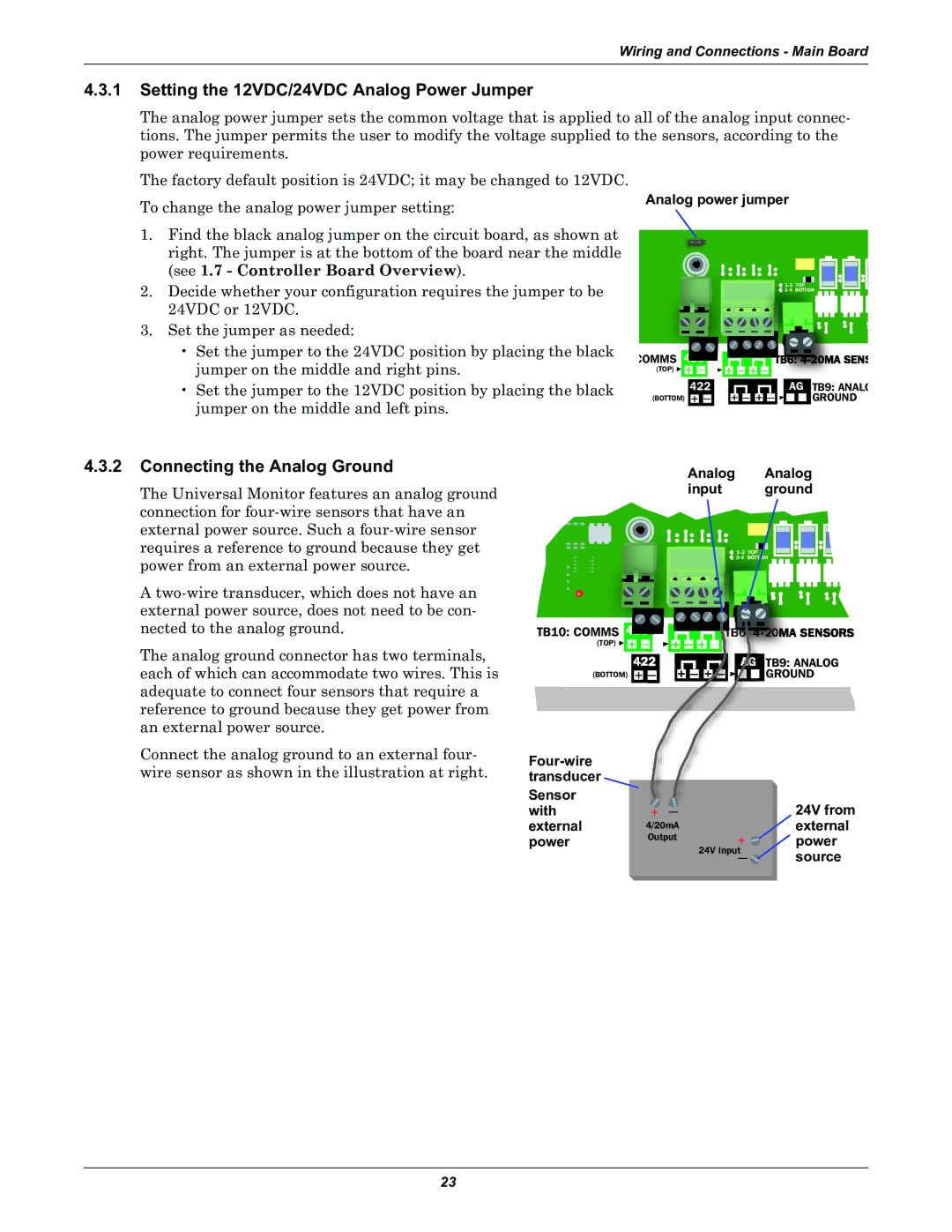
The analog power jumper sets the common voltage that is applied to all of the analog input connec- tions. The jumper permits the user to modify the voltage supplied to the sensors, according to the power requirements.
The factory default position is 24VDC; it may be changed to 12VDC.
To change the analog power jumper setting: | Analog power jumper |
|
| ||||||||||||||||||||
|
|
|
|
|
|
|
|
|
|
|
|
|
|
|
|
|
|
|
|
|
|
| |
1. Find the black analog jumper on the circuit board, as shown at |
|
|
|
|
|
|
|
|
|
|
|
|
|
|
|
|
|
|
|
|
|
|
|
right. The jumper is at the bottom of the board near the middle |
|
|
|
|
|
|
|
|
|
|
|
|
|
|
|
|
|
|
|
|
|
|
|
(see 1.7 - Controller Board Overview). |
|
|
|
|
|
|
|
|
|
|
|
|
|
|
|
|
|
|
|
|
|
|
|
2. Decide whether your configuration requires the jumper to be |
|
|
|
|
|
|
|
|
|
|
|
|
|
|
|
|
|
| |||||
24VDC or 12VDC. |
|
|
|
|
|
|
|
|
|
|
|
|
|
|
|
| |||||||
|
|
|
|
|
|
|
|
|
|
|
|
|
|
|
|
|
|
|
|
|
|
| |
|
|
|
|
|
|
|
|
|
|
|
|
|
|
|
|
|
|
|
|
|
|
| |
3. Set the jumper as needed: |
|
|
|
|
|
|
|
|
|
|
|
|
|
|
|
|
|
|
|
|
|
|
|
|
|
|
|
|
|
|
|
|
|
|
|
|
|
|
|
|
|
|
|
|
|
| |
• Set the jumper to the 24VDC position by placing the black | COMMS |
|
|
|
|
|
|
|
|
|
|
|
|
|
|
|
|
|
|
|
|
|
|
jumper on the middle and right pins. | (TOP) | + | — |
|
| + | — |
| + |
| — |
|
|
|
|
|
|
|
|
| |||
• Set the jumper to the 12VDC position by placing the black |
|
|
|
|
|
|
|
|
|
|
|
|
|
|
|
|
|
|
|
|
|
|
|
| 422 |
|
|
|
|
|
|
|
|
|
|
| AG | TB9: ANALO | |||||||||
jumper on the middle and left pins. | (BOTTOM) |
| + | — |
| + | — | + | — |
|
|
|
|
|
| GROUND | |||||||
|
|
|
|
|
|
|
|
|
|
|
|
|
|
|
|
|
|
|
|
|
|
| |
4.3.2 Connecting the Analog Ground |
|
|
|
|
|
|
|
|
|
|
|
|
|
| Analog | Analog | ||||
The Universal Monitor features an analog ground |
|
|
|
|
|
|
|
|
|
|
|
|
|
| input | ground | ||||
connection for |
|
|
|
|
|
|
|
|
|
|
|
|
|
|
|
|
|
|
|
|
external power source. Such a |
|
|
|
|
|
|
|
|
|
|
|
|
|
|
|
|
|
|
|
|
|
|
|
|
|
|
|
|
|
|
|
|
|
|
|
|
|
|
|
| |
requires a reference to ground because they get |
|
|
|
|
|
|
|
|
|
|
|
|
|
|
|
|
|
| ||
|
|
|
|
|
|
|
|
|
|
|
|
|
|
|
|
|
| |||
power from an external power source. |
|
|
|
|
|
|
|
|
|
|
|
|
|
|
|
|
|
|
| |
A |
|
|
|
|
|
|
|
|
|
|
|
|
|
|
|
|
|
|
|
|
|
|
|
|
|
|
|
|
|
|
|
|
|
|
|
|
|
|
|
| |
external power source, does not need to be con- |
|
|
|
|
|
|
|
|
|
|
|
|
|
|
|
|
|
|
|
|
nected to the analog ground. |
|
|
|
|
|
|
|
|
|
|
|
|
|
|
|
|
|
|
|
|
TB10: COMMS |
|
|
|
|
|
|
|
|
|
|
|
|
| |||||||
|
|
|
|
|
|
|
|
|
|
|
|
|
|
|
|
|
|
|
|
|
The analog ground connector has two terminals, |
|
| (TOP) | + |
|
|
|
|
|
|
|
|
|
| TB9: ANALOG | |||||
|
|
|
|
|
|
|
|
|
| |||||||||||
|
|
|
|
|
|
|
|
|
|
|
|
|
|
|
|
|
| |||
|
|
|
|
|
|
|
|
|
|
|
|
|
|
|
|
|
| |||
each of which can accommodate two wires. This is |
|
|
|
|
|
|
|
|
|
|
|
|
|
|
|
|
|
| ||
|
|
|
|
|
|
|
|
|
|
|
|
|
|
| GROUND | |||||
| (BOTTOM) | + |
|
|
|
|
|
|
|
| ||||||||||
adequate to connect four sensors that require a reference to ground because they get power from an external power source.
Connect the analog ground to an external four- wire sensor as shown in the illustration at right.
Sensor with external power
+ — |
| 24V from |
4/20mA |
| external |
Output | + | power |
|
| |
| 24V Input | source |
| — |
23