Wiring and Connections - Optional Expansion Board
5.3Connect to the Universal Monitor
Two steps are required to establish connection between the optional Expansion Board and the Uni- versal Monitor.
5.3.1Connect EIA485 Connectors to Main Board
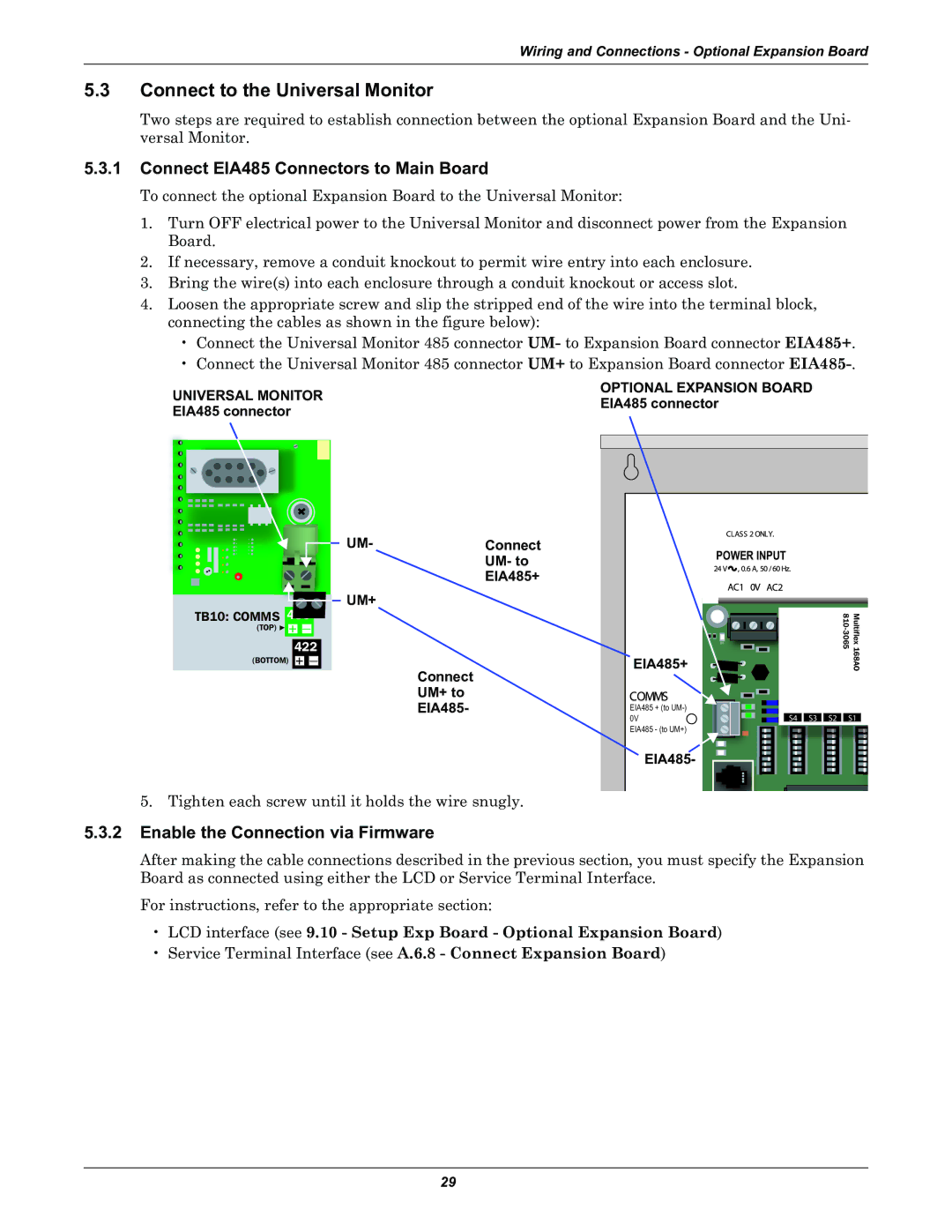
To connect the optional Expansion Board to the Universal Monitor:
1.Turn OFF electrical power to the Universal Monitor and disconnect power from the Expansion Board.
2.If necessary, remove a conduit knockout to permit wire entry into each enclosure.
3.Bring the wire(s) into each enclosure through a conduit knockout or access slot.
4.Loosen the appropriate screw and slip the stripped end of the wire into the terminal block, connecting the cables as shown in the figure below):
•Connect the Universal Monitor 485 connector UM- to Expansion Board connector EIA485+.
•Connect the Universal Monitor 485 connector UM+ to Expansion Board connector
UNIVERSAL MONITOR | OPTIONAL EXPANSION BOARD | |||
EIA485 connector | ||||
EIA485 connector | ||||
|
| |||
|
|
|
| |
|
|
|
| |
|
|
|
| |
UM- | Connect |
| UM- to |
| EIA485+ |
UM+ |
|
TB10: COMMS 485
(TOP) + —
422
(BOTTOM) + —
Connect
UM+ to
EIA485-
5. Tighten each screw until it holds the wire snugly.
| POWER INPUT |
|
|
EIA485+ | D6 | Multiflex168AO |
EIA485 + (to
0V | S4 | S3 | S2 | S1 |
EIA485 - (to UM+)
![]() EIA485-
EIA485-
5.3.2Enable the Connection via Firmware
After making the cable connections described in the previous section, you must specify the Expansion Board as connected using either the LCD or Service Terminal Interface.
For instructions, refer to the appropriate section:
•LCD interface (see 9.10 - Setup Exp Board - Optional Expansion Board)
•Service Terminal Interface (see A.6.8 - Connect Expansion Board)
29
