Wiring and Connections - Optional Expansion Board
5.2Connecting Inputs and Outputs
The Universal Monitor’s optional Expansion Board permits the addition of 16 input and eight output devices. This section describes how to connect devices to the Expansion Board’s inputs and outputs.
To determine the proper wire size, see Table 9.
NOTE
Each terminal block is a removable assembly to permit easier connection of more than one input at a time. If making multiple connections, grasp the upper portion of a block and pull firmly until the assembly pulls apart.
After making the connections, push the removed piece back into the portion attached to the printed wiring assembly until the terminal block pieces lock together.
5.2.1Connecting Digital Inputs
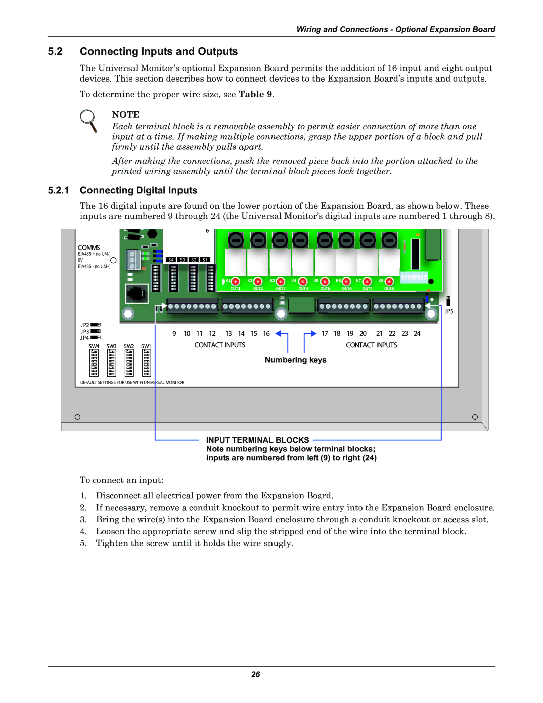
The 16 digital inputs are found on the lower portion of the Expansion Board, as shown below. These inputs are numbered 9 through 24 (the Universal Monitor’s digital inputs are numbered 1 through 8).
|
|
|
| V5 | V11 |
EIA485 + (to |
|
|
|
|
|
0V | S4 | S3 | S2 | S1 |
|
EIA485 - (to UM+)
K1 | K2 | K3 | K4 | K5 | K6 |
| K7 | K8 |
| OUT1 | OUT2 | OUT3 | OUT4 | OUT5 | OUT6 | OUT7 | OUT8 |
Numbering keys
DEFAULT SETTINGS FOR USE WITH UNIVERSAL MONITOR
INPUT TERMINAL BLOCKS
Note numbering keys below terminal blocks; inputs are numbered from left (9) to right (24)
To connect an input:
1.Disconnect all electrical power from the Expansion Board.
2.If necessary, remove a conduit knockout to permit wire entry into the Expansion Board enclosure.
3.Bring the wire(s) into the Expansion Board enclosure through a conduit knockout or access slot.
4.Loosen the appropriate screw and slip the stripped end of the wire into the terminal block.
5.Tighten the screw until it holds the wire snugly.
26