Introduction
1.6Typical Configuration
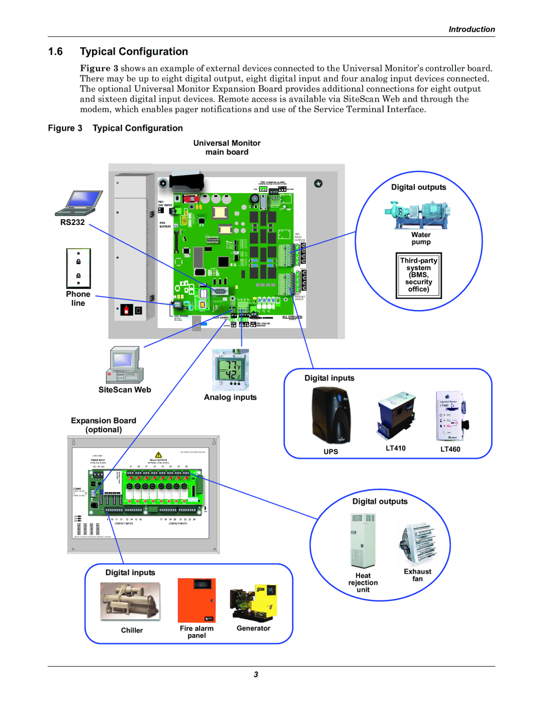
Figure 3 shows an example of external devices connected to the Universal Monitor’s controller board. There may be up to eight digital output, eight digital input and four analog input devices connected. The optional Universal Monitor Expansion Board provides additional connections for eight output and sixteen digital input devices. Remote access is available via SiteScan Web and through the modem, which enables pager notifications and use of the Service Terminal Interface.
Figure 3 Typical Configuration
Universal Monitor
main board
RS232
Phone
line
|
| TB5: COMMON ALARM | |
|
| (TERMINAL BLOCKS ROTATED IN VIEW) | |
|
| NO C NC | NO C NC |
|
| (TOP) | (BOTTOM) |
|
|
| OM |
|
| + |
|
TB7: | START | ENABLE |
|
24V INPUT |
| AUDIBLE |
|
|
|
| |
|
| Q11 |
|
|
|
| TOP |
P23: | BATTERY | BARCODE | LIEBERT |
|
|
|
BATTERY |
|
|
|
|
|
|
|
| LCD |
|
|
|
|
|
| CONTRAST |
|
|
|
|
|
|
|
|
|
| TB3: |
|
| VBATT |
|
|
| RELAY |
|
|
|
|
|
| |
|
|
|
|
|
| OUTPUTS |
|
|
|
|
|
| (BOTTOM) |
|
|
|
|
|
| (TOP) |
|
|
|
| CAN TX |
| 8 |
|
|
|
| CAN RX |
| 4 |
|
|
|
|
|
| 7 |
|
|
|
|
|
| 3 |
|
|
|
|
|
| 6 |
|
|
|
| ON OFF |
| 2 |
|
|
|
| PFM2 | 5 | |
|
|
|
| ON OFF |
| 1 |
|
|
|
| PFM5 |
| |
|
|
| MODEM | REV | (BOTTOM) | |
|
|
|
|
| (TOP) | |
|
|
| 4 | D |
| 8 |
|
|
|
|
|
| 4 |
|
|
|
|
|
| 7 |
|
|
|
|
|
| 3 |
|
|
|
|
|
| 6 |
|
|
|
|
|
| 2 |
|
|
|
|
|
| 5 |
|
|
|
|
|
| 1 |
|
|
|
|
|
| TB2: |
|
|
|
|
|
| CONTACT |
|
|
|
|
|
| INPUTS |
|
|
|
|
|
| |
|
|
|
|
|
| |
ON |
MODEM |
J11: PHONE | COMMS 485 |
|
| ALL |
PIN |
|
| ||
PIN | (TOP) + — | + — + — |
| CLASS 2 |
| 422 |
| AG | TB9: ANALOG |
| (BOTTOM) + — | + — + — |
| GROUND |
Digital outputs
Water pump
system
(BMS,
security
office)
Digital inputs
SiteScan Web
Analog inputs
Expansion Board
(optional)
EIA485 + (to
0V![]() EIA485 - (to UM+)
EIA485 - (to UM+)
USE COPPER (CU) CONDUCTORS ONLY.
POWER INPUT | RELAY OUTPUTS |
Multiflex168AO | V2 |
| V4 | V6 | V8 | V10 | V12 | V14 | V16 | |
V1 | V3 | V5 |
| V7 | V9 | V11 | V13 | V15 | ||
|
|
|
|
|
|
|
|
|
S4 | S3 | S2 | S1 |
K1 | K2 | K3 | K4 | K5 | K6 |
| K7 | K8 |
| OUT1 | OUT2 | OUT3 | OUT4 | OUT5 | OUT6 | OUT7 | OUT8 |
UPSLT410 LT460
Digital outputs
DEFAULT SETTINGS FOR USE WITH UNIVERSAL MONITOR
Digital inputs |
| Heat | Exhaust |
|
| rejection | fan |
|
| unit |
|
Chiller | Fire alarm | Generator |
|
| panel |
|
|
3