View Status Options
7.5View Input Status
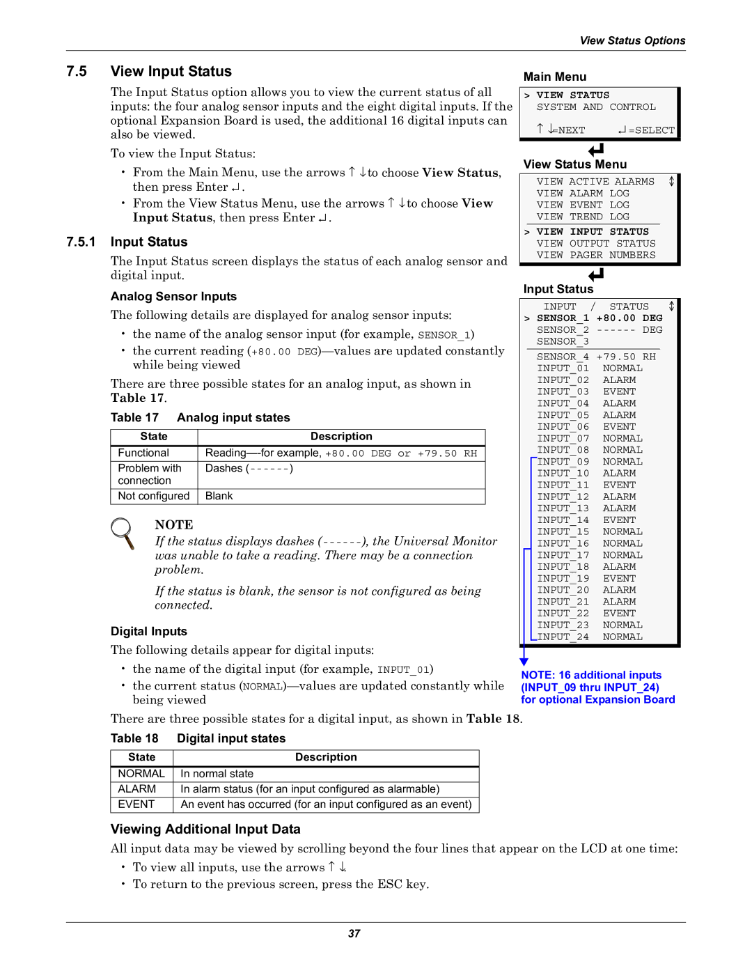
The Input Status option allows you to view the current status of all inputs: the four analog sensor inputs and the eight digital inputs. If the optional Expansion Board is used, the additional 16 digital inputs can also be viewed.
To view the Input Status:
•From the Main Menu, use the arrows ↑ ↓ to choose View Status, then press Enter ↵ .
•From the View Status Menu, use the arrows ↑ ↓ to choose View Input Status, then press Enter ↵ .
7.5.1Input Status
The Input Status screen displays the status of each analog sensor and digital input.
Analog Sensor Inputs
The following details are displayed for analog sensor inputs:
•the name of the analog sensor input (for example, SENSOR_1)
•the current reading (+80.00
There are three possible states for an analog input, as shown in Table 17.
Table 17 Analog input states
State | Description |
Functional | |
Problem with | Dashes |
connection |
|
Not configured | Blank |
NOTE
If the status displays dashes
was unable to take a reading. There may be a connection problem.
If the status is blank, the sensor is not configured as being connected.
Digital Inputs
The following details appear for digital inputs:
Main Menu
>VIEW STATUS SYSTEM AND CONTROL
↑ ↓=NEXT | ↵ =SELECT |
View Status Menu
VIEW ACTIVE ALARMS
VIEW ALARM LOG
VIEW EVENT LOG
VIEW TREND LOG
>VIEW INPUT STATUS VIEW OUTPUT STATUS VIEW PAGER NUMBERS
Input Status
INPUT | / | STATUS | |
> SENSOR_1 +80.00 | DEG | ||
SENSOR_2 | DEG | ||
SENSOR_3 |
|
|
|
SENSOR_4 +79.50 | RH | ||
INPUT_01 |
| NORMAL |
|
INPUT_02 |
| ALARM |
|
INPUT_03 |
| EVENT |
|
INPUT_04 |
| ALARM |
|
INPUT_05 |
| ALARM |
|
INPUT_06 |
| EVENT |
|
INPUT_07 |
| NORMAL |
|
INPUT_08 |
| NORMAL |
|
INPUT_09 |
| NORMAL |
|
INPUT_10 |
| ALARM |
|
INPUT_11 |
| EVENT |
|
INPUT_12 |
| ALARM |
|
INPUT_13 |
| ALARM |
|
INPUT_14 |
| EVENT |
|
INPUT_15 |
| NORMAL |
|
INPUT_16 |
| NORMAL |
|
INPUT_17 |
| NORMAL |
|
INPUT_18 |
| ALARM |
|
INPUT_19 |
| EVENT |
|
INPUT_20 |
| ALARM |
|
INPUT_21 |
| ALARM |
|
INPUT_22 |
| EVENT |
|
INPUT_23 |
| NORMAL |
|
INPUT_24 |
| NORMAL |
|
•the name of the digital input (for example, INPUT_01)
•the current status
NOTE: 16 additional inputs (INPUT_09 thru INPUT_24) for optional Expansion Board
There are three possible states for a digital input, as shown in Table 18.
Table 18 Digital input states
State | Description |
NORMAL | In normal state |
ALARM | In alarm status (for an input configured as alarmable) |
EVENT | An event has occurred (for an input configured as an event) |
Viewing Additional Input Data
All input data may be viewed by scrolling beyond the four lines that appear on the LCD at one time:
•To view all inputs, use the arrows ↑ ↓.
•To return to the previous screen, press the ESC key.
37
