Introduction
1.8Optional Expansion Board Overview
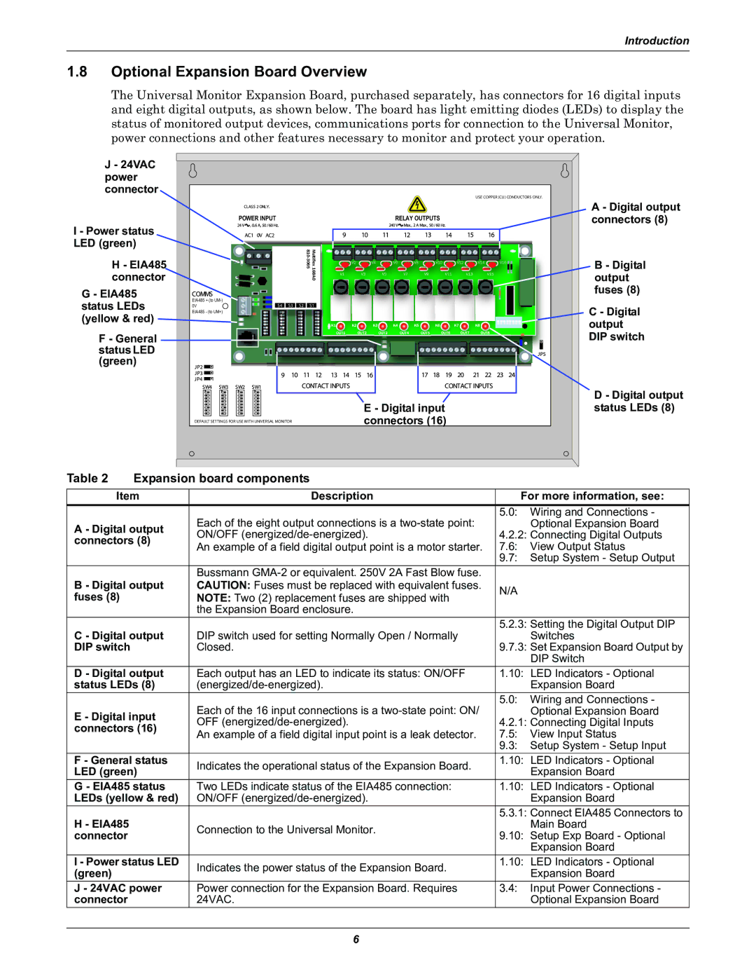
The Universal Monitor Expansion Board, purchased separately, has connectors for 16 digital inputs and eight digital outputs, as shown below. The board has light emitting diodes (LEDs) to display the status of monitored output devices, communications ports for connection to the Universal Monitor, power connections and other features necessary to monitor and protect your operation.
J - 24VAC power connector
I - Power status LED (green)
H - EIA485 connector
G - EIA485 status LEDs (yellow & red)
F - General status LED (green)
USE COPPER (CU) CONDUCTORS ONLY.
POWER INPUT | RELAY OUTPUTS |
|
|
| V2 | V4 | V6 | V8 | V10 | V12 | V14 | V16 |
D6 |
|
|
|
|
|
|
|
|
| |
| V1 | V3 | V5 |
| V7 | V9 | V11 | V13 | V15 | |
| 168AOMultiflex |
|
|
|
|
|
|
|
|
EIA485 + (to
0V | S4 | S3 | S2 | S1 |
EIA485 - (to UM+)
K1 | K2 | K3 | K4 | K5 | K6 |
| K7 | K8 |
| OUT1 | OUT2 | OUT3 | OUT4 | OUT5 | OUT6 | OUT7 | OUT8 |
| E - Digital input |
DEFAULT SETTINGS FOR USE WITH UNIVERSAL MONITOR | connectors (16) |
A - Digital output connectors (8)
B - Digital output fuses (8)
C - Digital output DIP switch
D - Digital output status LEDs (8)
Table 2 | Expansion board components |
|
| ||
Item | Description | For more information, see: | |||
|
| Each of the eight output connections is a | 5.0: | Wiring and Connections - | |
A - Digital output |
| Optional Expansion Board | |||
ON/OFF | 4.2.2: Connecting Digital Outputs | ||||
connectors (8) | |||||
An example of a field digital output point is a motor starter. | 7.6: | View Output Status | |||
|
| ||||
|
|
| 9.7: | Setup System - Setup Output | |
|
| Bussmann |
|
| |
B - Digital output | CAUTION: Fuses must be replaced with equivalent fuses. | N/A |
| ||
fuses (8) |
| NOTE: Two (2) replacement fuses are shipped with |
| ||
|
|
| |||
|
| the Expansion Board enclosure. |
|
| |
C - Digital output | DIP switch used for setting Normally Open / Normally | 5.2.3: Setting the Digital Output DIP | |||
| Switches | ||||
DIP switch |
| Closed. | 9.7.3: Set Expansion Board Output by | ||
|
|
|
| DIP Switch | |
D - Digital output | Each output has an LED to indicate its status: ON/OFF | 1.10: LED Indicators - Optional | |||
status LEDs (8) |
| Expansion Board | |||
|
| Each of the 16 input connections is a | 5.0: | Wiring and Connections - | |
E - Digital input |
| Optional Expansion Board | |||
OFF | 4.2.1: Connecting Digital Inputs | ||||
connectors (16) | |||||
An example of a field digital input point is a leak detector. | 7.5: | View Input Status | |||
|
| ||||
|
|
| 9.3: | Setup System - Setup Input | |
F - General status | Indicates the operational status of the Expansion Board. | 1.10: LED Indicators - Optional | |||
LED (green) |
| Expansion Board | |||
|
| ||||
G - EIA485 status | Two LEDs indicate status of the EIA485 connection: | 1.10: LED Indicators - Optional | |||
LEDs (yellow & red) | ON/OFF |
| Expansion Board | ||
H - EIA485 |
|
| 5.3.1: Connect EIA485 Connectors to | ||
| Connection to the Universal Monitor. |
| Main Board | ||
connector |
| 9.10: Setup Exp Board - Optional | |||
|
| ||||
|
|
|
| Expansion Board | |
I - Power status LED | Indicates the power status of the Expansion Board. | 1.10: LED Indicators - Optional | |||
(green) |
|
| Expansion Board | ||
|
|
| |||
J - 24VAC power | Power connection for the Expansion Board. Requires | 3.4: | Input Power Connections - | ||
connector |
| 24VAC. |
| Optional Expansion Board | |
6
