Return to Section TOC
Return to Master TOC
F-28 TROUBLESHOOTING & REPAIRF-28
ENGINE ALTERNATOR TEST (CONTINUED)
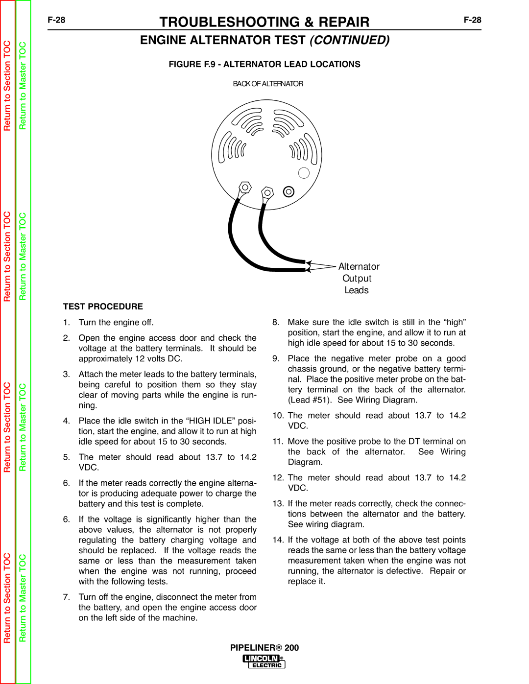
FIGURE F.9 - ALTERNATOR LEAD LOCATIONS
BACK OF ALTERNATOR
Return to Section TOC
Return to Section TOC
to Section TOC
Return to Master TOC
Return to Master TOC
Return to Master TOC
TEST PROCEDURE
1. Turn the engine off.
2. Open the engine access door and check the voltage at the battery terminals. It should be approximately 12 volts DC.
3. Attach the meter leads to the battery terminals, being careful to position them so they stay clear of moving parts while the engine is run- ning.
4. Place the idle switch in the “HIGH IDLE” posi- tion, start the engine, and allow it to run at high idle speed for about 15 to 30 seconds.
5. The meter should read about 13.7 to 14.2 VDC.
6. If the meter reads correctly the engine alterna- tor is producing adequate power to charge the battery and this test is complete.
6. If the voltage is significantly higher than the above values, the alternator is not properly regulating the battery charging voltage and should be replaced. If the voltage reads the same or less than the measurement taken when the engine was not running, proceed with the following tests.
7. Turn off the engine, disconnect the meter from the battery, and open the engine access door on the left side of the machine.
 Alternator
Output
Leads
8.Make sure the idle switch is still in the “high” position, start the engine, and allow it to run at high idle speed for about 15 to 30 seconds.
9.Place the negative meter probe on a good chassis ground, or the negative battery termi- nal. Place the positive meter probe on the bat- tery terminal on the back of the alternator. (Lead #51). See Wiring Diagram.
10.The meter should read about 13.7 to 14.2 VDC.
11.Move the positive probe to the DT terminal on the back of the alternator. See Wiring Diagram.
12.The meter should read about 13.7 to 14.2 VDC.
13.If the meter reads correctly, check the connec- tions between the alternator and the battery. See wiring diagram.
14.If the voltage at both of the above test points reads the same or less than the battery voltage measurement taken when the engine was not running, the alternator is defective. Repair or replace it.
Return