Return to Section TOC
Return to Section TOC
Return to Section TOC
Return to Section TOC
TROUBLESHOOTING & REPAIR | ||
TOC | IDLER SOLENOID TEST (continued) |
|
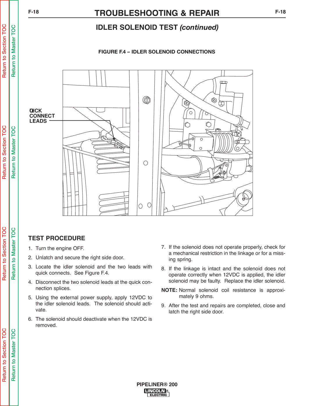
Master | FIGURE F.4 – IDLER SOLENOID CONNECTIONS |
|
Return to |
| |
|
| |
QUICK |
|
|
CONNECT |
|
|
LEADS |
|
|
Return to Master TOC |
|
|
TOC | TEST PROCEDURE | 7. | If the solenoid does not operate properly, check for | |
Masterto | 1. | Turn the engine OFF. | ||
2. | Unlatch and secure the right side door. |
| ing spring. | |
| 3. | Locate the idler solenoid and the two leads with |
| a mechanical restriction in the linkage or for a miss- |
Return | 8. | If the linkage is intact and the solenoid does not | ||
4. | quick connects. See Figure F.4. |
| operate correctly when 12VDC is applied, the idler | |
| Disconnect the two solenoid leads at the quick con- |
| solenoid may be faulty. Replace the idler solenoid. | |
| 5. | nection splices. | NOTE: Normal solenoid coil resistance is approxi- | |
| Using the external power supply, apply 12VDC to | 9. | mately 9 ohms. | |
|
| the idler solenoid leads. The solenoid should acti- | After the test and repairs are completed, close and | |
| 6. | vate. |
| latch the right side door. |
| The solenoid should deactivate when the 12VDC is |
| ||
Return to Master TOC |
| removed. |
|
|
| PIPELINER® 200 | |||
|
| |||