Return to Section TOC
Return to Section TOC
Return to Section TOC
Return to Section TOC
Return to Master TOC
Return to Master TOC
Return to Master TOC
Return to Master TOC
| TROUBLESHOOTING & REPAIR | ||||
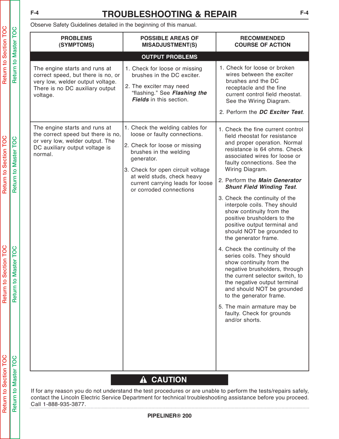
| Observe Safety Guidelines detailed in the beginning of this manual. |
|
| ||
|
| PROBLEMS | POSSIBLE AREAS OF | RECOMMENDED |
|
|
|
| |||
|
| (SYMPTOMS) | MISADJUSTMENT(S) | COURSE OF ACTION |
|
| The engine starts and runs at | OUTPUT PROBLEMS | 1. Check for loose or broken |
| |
|
| ||||
| 1. Check for loose or missing |
| |||
| correct speed, but there is no, or | brushes in the DC exciter. | wires between the exciter |
| |
| very low, welder output voltage. | 2. The exciter may need | brushes and the DC |
| |
| There is no DC auxiliary output | receptacle and the fine |
| ||
| “flashing.” See Flashing the | current control field rheostat. | |||
| voltage. |
| Fields in this section. | See the Wiring Diagram. |
|
|
|
|
| 2. Perform the DC Exciter Test. | |
| The engine starts and runs at | 1. Check the welding cables for | 1. Check the fine current control | ||
| the correct speed but there is no, | loose or faulty connections. | field rheostat for resistance |
| |
| or very low, welder output. The | 2. Check for loose or missing | and proper operation. Normal | ||
| DC auxiliary output voltage is | resistance is 64 ohms. Check | |||
| normal. |
| brushes in the welding | associated wires for loose or | |
|
|
| generator. | faulty connections. See the |
|
|
|
| 3. Check for open circuit voltage | Wiring Diagram. |
|
|
|
| at weld studs, check heavy | 2. Perform the Main Generator | |
|
|
| current carrying leads for loose | Shunt Field Winding Test. |
|
|
|
| or corroded connections | 3. Check the continuity of the |
|
|
|
|
| interpole coils. They should |
|
|
|
|
| show continuity from the |
|
|
|
|
| positive brusholders to the |
|
|
|
|
| positive output terminal and |
|
|
|
|
| should NOT be grounded to |
|
|
|
|
| the generator frame. |
|
|
|
|
| 4. Check the continuity of the |
|
|
|
|
| series coils. They should |
|
|
|
|
| show continuity from the |
|
|
|
|
| negative brusholders, through | |
|
|
|
| the current selector switch, to | |
|
|
|
| the negative output terminal |
|
|
|
|
| and should NOT be grounded | |
|
|
|
| to the generator frame. |
|
|
|
|
| 5. The main armature may be |
|
|
|
|
| faulty. Check for grounds |
|
|
|
|
| and/or shorts. |
|
CAUTION
If for any reason you do not understand the test procedures or are unable to perform the tests/repairs safely, contact the Lincoln Electric Service Department for technical troubleshooting assistance before you proceed. Call