Return to Section TOC
Return to Section TOC
Return to Section TOC
Return to Section TOC
Return to Master TOC
Return to Master TOC
Return to Master TOC
Return to Master TOC
THEORY OF OPERATION | ||
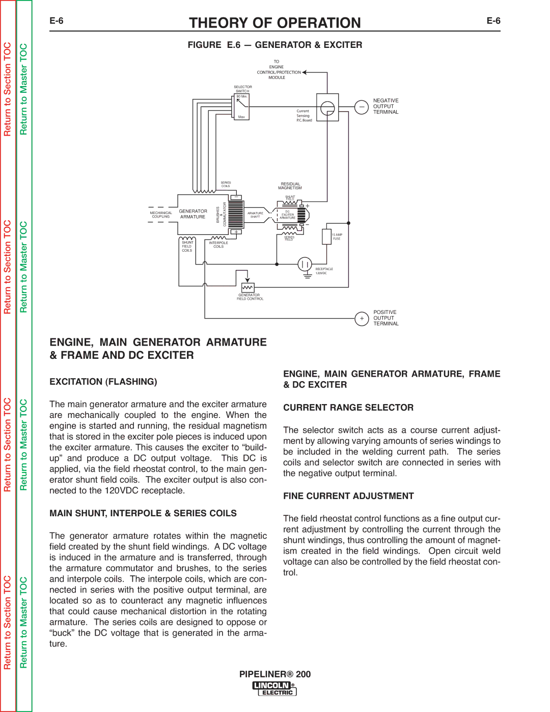
| FIGURE E.6 — GENERATOR & EXCITER |
|
|
|
|
|
| TO |
|
|
|
|
|
|
| ENGINE |
|
|
|
|
|
| CONTROL/PROTECTION |
|
| |
|
|
|
|
| MODULE |
|
|
|
|
|
| SELECTOR |
|
|
|
|
|
|
| SWITCH |
|
|
|
|
|
|
| 90 Min. |
|
| NEGATIVE |
|
|
|
|
|
| - | |
|
|
|
|
|
| OUTPUT | |
|
|
|
|
| Current |
| TERMINAL |
|
|
|
| Max | Sensing |
|
|
|
|
|
|
| P.C. Board |
|
|
|
|
| SERIES |
| RESIDUAL |
|
|
|
|
| COILS |
|
|
| |
|
|
|
| _ | MAGNETISM |
|
|
|
|
|
| SHUNT |
|
| |
|
| BRUSHES | COMMUTATOR |
| FIELD |
|
|
|
|
| - |
|
| ||
| GENERATOR |
|
|
| + |
|
|
MECHANICAL | & | ARMATURE | DC |
|
| ||
COUPLING | ARMATURE | SHAFT | EXCITER |
|
| ||
|
| ARMATURE |
|
| |||
|
|
|
| + | SERIES | 15 AMP |
|
|
|
|
|
|
| ||
|
|
|
|
| FUSE |
| |
| SHUNT | INTERPOLE |
| FIELD |
| ||
|
|
|
|
| |||
| FIELD | COILS |
|
|
|
| |
| COILS |
|
|
|
|
|
|
|
|
|
|
|
| RECEPTACLE |
|
|
|
|
|
|
| 120VDC |
|
|
|
|
| GENERATOR |
|
|
|
|
|
|
| FIELD CONTROL |
|
|
|
|
|
|
|
|
| + | POSITIVE |
|
|
|
|
|
| OUTPUT | |
ENGINE, MAIN GENERATOR ARMATURE |
|
| TERMINAL | ||||
|
|
| |||||
& FRAME AND DC EXCITER |
|
|
| ENGINE, MAIN GENERATOR ARMATURE, FRAME | |||
EXCITATION (FLASHING) |
|
|
|
| |||
|
|
|
| & DC EXCITER |
| ||
The main generator armature and the exciter armature | CURRENT RANGE SELECTOR | ||||||
are mechanically coupled to the engine. When the | |||||||
engine is started and running, the residual magnetism | The selector switch acts as a course current adjust- | ||||||
that is stored in the exciter pole pieces is induced upon | |||||||
the exciter armature. This causes the exciter to “build- | ment by allowing varying amounts of series windings to | ||||||
up” and produce a DC output voltage. | This DC is | be included in the welding current path. The series | |||||
applied, via the field rheostat control, to the main gen- | coils and selector switch are connected in series with | ||||||
erator shunt field coils. The exciter output is also con- | the negative output terminal. | ||||||
nected to the 120VDC receptacle. |
|
|
| FINE CURRENT ADJUSTMENT | |||
MAIN SHUNT, INTERPOLE & SERIES COILS | The field rheostat control functions as a fine output cur- | ||||||
The generator armature rotates within the magnetic | rent adjustment by controlling the current through the | ||||||
field created by the shunt field windings. A DC voltage | shunt windings, thus controlling the amount of magnet- | ||||||
is induced in the armature and is transferred, through | ism created in the field windings. Open circuit weld | ||||||
the armature commutator and brushes, to the series | voltage can also be controlled by the field rheostat con- | ||||||
and interpole coils. The interpole coils, which are con- | trol. |
|
| ||||
nected in series with the positive output terminal, are |
|
|
| ||||
located so as to counteract any magnetic influences |
|
|
| ||||
that could cause mechanical distortion in the rotating |
|
|
| ||||
armature. The series coils are designed to oppose or |
|
|
| ||||
“buck” the DC voltage that is generated in the arma- |
|
|
| ||||
ture. |
|
|
|
|
|
|
|
|
|
|
| PIPELINER® 200 |
|
| |