Return to Section TOC
Return to Section TOC
Return to Master TOC
Return to Master TOC
F-56 TROUBLESHOOTING & REPAIRF-56
MAIN GENERATOR FRAME REMOVAL AND REPLACEMENT PROCEDURE
(CONTINUED)
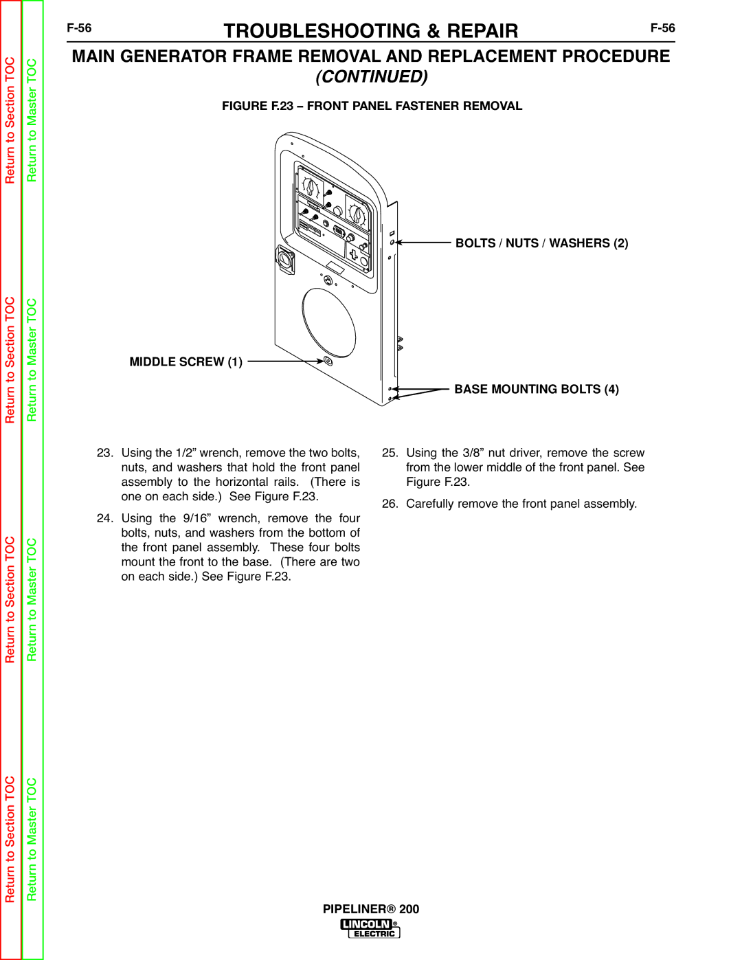
FIGURE F.23 – FRONT PANEL FASTENER REMOVAL

 BOLTS / NUTS / WASHERS (2)
MIDDLE SCREW (1) 


 BASE MOUNTING BOLTS (4)
Return to Section TOC
Return to Master TOC
23.Using the 1/2” wrench, remove the two bolts, nuts, and washers that hold the front panel assembly to the horizontal rails. (There is one on each side.) See Figure F.23.
24.Using the 9/16” wrench, remove the four bolts, nuts, and washers from the bottom of the front panel assembly. These four bolts mount the front to the base. (There are two on each side.) See Figure F.23.
25.Using the 3/8” nut driver, remove the screw from the lower middle of the front panel. See Figure F.23.
26.Carefully remove the front panel assembly.
Return to Section TOC
Return to Master TOC
