to Section TOC
Return to Master TOC
F-16 TROUBLESHOOTING & REPAIRF-16
DC EXCITER TEST (continued)
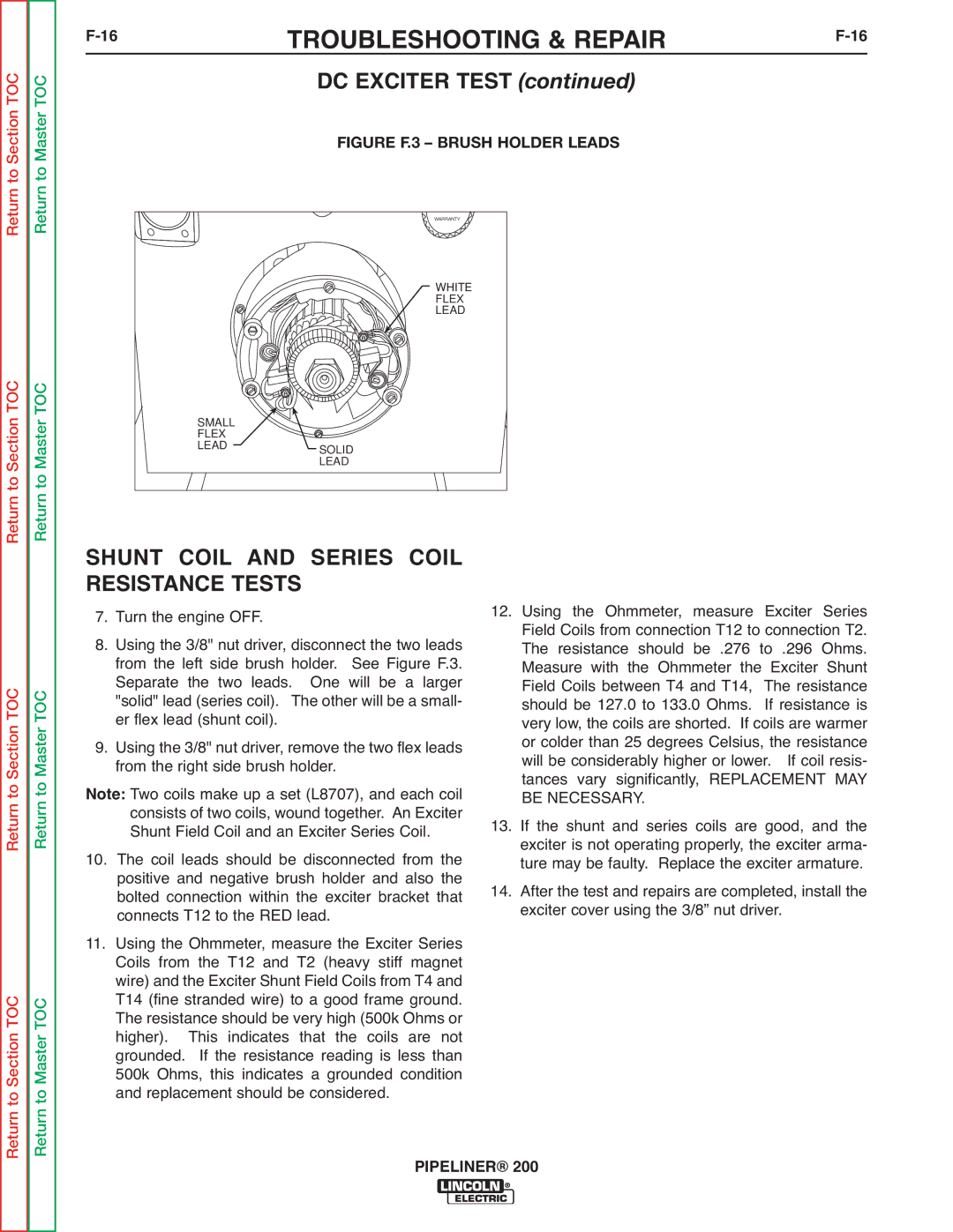
FIGURE F.3 – BRUSH HOLDER LEADS
Return
to Section TOC
to Master TOC
| WARRANTY |
| WHITE |
| FLEX |
| LEAD |
SMALL |
|
FLEX |
|
LEAD | SOLID |
| |
| LEAD |
|
|
| RED LEAD - |
|
| #2 |
|
|
|
| EXCITER |
|
|
| EXCITER SERIES FIELD | ARMATURE |
| 120 VOLTS | ||
| - | + | DC | |||
|
|
|
| #1 | ||
T12 | T11 | T1 | T2 |
|
| |
|
|
| ||||
|
|
| T 4 | T3 T13 |
| T14 |
|
|
|
| EXCITER SHUNT FIELD |
| |
Return
Return to Section TOC
to Section TOC
Return
Return to Master TOC
Return to Master TOC
SHUNT COIL AND SERIES COIL RESISTANCE TESTS
7. Turn the engine OFF.
8. Using the 3/8" nut driver, disconnect the two leads from the left side brush holder. See Figure F.3. Separate the two leads. One will be a larger "solid" lead (series coil). The other will be a small- er flex lead (shunt coil).
9. Using the 3/8" nut driver, remove the two flex leads from the right side brush holder.
Note: Two coils make up a set (L8707), and each coil consists of two coils, wound together. An Exciter Shunt Field Coil and an Exciter Series Coil.
10. The coil leads should be disconnected from the positive and negative brush holder and also the bolted connection within the exciter bracket that connects T12 to the RED lead.
11. Using the Ohmmeter, measure the Exciter Series Coils from the T12 and T2 (heavy stiff magnet wire) and the Exciter Shunt Field Coils from T4 and T14 (fine stranded wire) to a good frame ground. The resistance should be very high (500k Ohms or higher). This indicates that the coils are not grounded. If the resistance reading is less than 500k Ohms, this indicates a grounded condition and replacement should be considered.
12.Using the Ohmmeter, measure Exciter Series Field Coils from connection T12 to connection T2. The resistance should be .276 to .296 Ohms. Measure with the Ohmmeter the Exciter Shunt Field Coils between T4 and T14, The resistance should be 127.0 to 133.0 Ohms. If resistance is very low, the coils are shorted. If coils are warmer or colder than 25 degrees Celsius, the resistance will be considerably higher or lower. If coil resis- tances vary significantly, REPLACEMENT MAY BE NECESSARY.
13.If the shunt and series coils are good, and the exciter is not operating properly, the exciter arma- ture may be faulty. Replace the exciter armature.
14.After the test and repairs are completed, install the exciter cover using the 3/8” nut driver.
Return