BCM200/400 4.0 Installation and Maintenance Guide
Trademarks
Copyright 2006 Nortel Networks, All Rights Reserved
Software License
BCM200/400 4.0 Installation and Maintenance Guide
N0060612
Task List
Task List
Completing the initial installation optional
Replacing a media bay module
Replacing or installing a cooling fan 323
Contents
Chapter Viewing the BCM system LEDs
Chapter Installing an expansion unit
Chapter Installing telephones and peripherals
Chapter Configuring the BCM system
Chapter Replacing a media bay module
Chapter Replacing or upgrading a power supply
Index
Regulatory information
North American regulatory information
Canadian Notice
Regulatory information
Federal Communications Commission FCC Notice
Ringer Equivalence Number REN
EMI/EMC FCC Part
Important safety instructions
Installation
Use
Use of a music source
Safety
Enhanced 911 configuration
Radio-frequency interference
Telecommunication registration
International regulatory information
Additional safety information
ITU standardization compliance
Acronyms
Getting started
About this guide
Audience
Acronym Description
Getting started Acronyms Sheet 2
Getting started Acronyms Sheet 3
Symbols and conventions used in this guide
Convention Example Used for
Getting started
Related publications
Technical Documents
User Guides
Getting Help through a Nortel distributor or reseller
How to get help
Getting Help over the phone from a Nortel Solutions Center
Getting Help from the Nortel Web site
Main units
Introducing the BCM hardware
Component Description
BCM200 main unit
Introducing the BCM hardware
BCM200 main unit component descriptions
BCM200 main unit internal component descriptions
BCM200 main unit internal components
BCM400 main unit component descriptions
BCM400 main unit
BCM400 main unit internal components standard configuration
BCM400 main unit internal components RFO configuration
BCM400 advanced function tray
Component Description Front view
Rear view
Advanced function tray
BCM400 advanced function tray RAID status LEDs
Base function tray faceplate components
Base function tray component hardware
Base function tray internal components
Base function tray internal components
BCM200 MSC components
Media services card MSC
Connectors Description
MSC faceplate optional connectors
MSC IP call processing hardware
Main card
Main card connections
Main card connectors installed in the base function tray
Chapter Introducing the BCM hardware
PCI riser card
WAN interface card
Data networking components
WAN interface card international version
Modem card
Interface card
BCM expansion unit BCM400 only
O interface card connectors
BCM expansion unit connected to BCM400 main unit
MBM bays and backplane
BCM200 MBM backplane
Media bay modules MBMs
Telephony hardware components
Trunk media bay modules MBMs
Trunk MBMs Sheet 1
What it does Special notes
Introducing the BCM hardware Trunk MBMs Sheet 2
Digital trunk media bay module
Basic rate interface media bay module
Caller ID trunk media bay module
Station media bay modules MBMs
Global analog trunk media bay module
Station MBMs Sheet 1
Digital station media bay module
Chapter Introducing the BCM hardware Station MBMs Sheet 2
DSM 16+ DSM 32+
Analog station media bay modules
4x16 media bay module
ATA2 ASM8 ASM8+ GASM8 Gasi
OSI EIA/TIA
Specialized MBMs
Specialized media bay modules MBMs
Fiber expansion media bay module
Digital drop and insert MUX
BCM400 expansion gateway
Ddim faceplate LEDs and connectors
BCM components
BCM power supply
Standard power supply connectors
BCM400 redundant power supply
BCM400 redundant power supply and modules
Power supply adapter cord international users
Uninterruptable power supply
Hard disk
BCM200 main unit hard disk and bracket
RAID upgrade kit
Cooling fan
Field replaceable units FRU
Introducing the BCM hardware Cooling fan
Card field replaceable units
Power supply field replaceable units
Hard drive field replaceable units
Cooling fan field replaceable units
MBM
Telephones and adapters
Pqrs
Introducing the BCM hardware
Accessories
Introducing the BCM hardware N0060612
Base function tray system status LED states Sheet 1
Viewing the BCM system LEDs
Base function tray system status display LEDs
Viewing the BCM system LEDs
MSC
Power LED Status LED Description
Media bay module LEDs
Base function tray system status LED states Sheet 3
Power Status Description
DTM LEDs
MBM LED descriptions
Status Descriptions
DTM LED functions
Brim LED functions
Brim LEDs
Installation overview
Installation overview
Supplies, and tools on
Tasks Description Link to
Initializing the system on
Installation overview N0060612
Environmental requirements
Checking the installation prerequisites
Checking the installation prerequisites
General requirements
Site telephony wiring requirements
Electrical requirements
Digital loop
Optional equipment
System equipment, supplies, and tools
Analog loop
Basic hardware
Other hardware and tools
Shows the steps required to install the main unit
Installing the BCM main unit
Installing the main unit in an equipment rack
Installing the BCM main unit
Unpacking the main unit
Attach the rack-mount bracket to the BCM200 main unit
To attach the rack-mount brackets
Attach the rack-mount bracket to the BCM400 main unit
To mount the main unit in an equipment rack
Fasten the BCM200 main unit to an equipment rack
To install the main unit on the wall
Installing the main unit on the wall
Installing the BCM main unit
Attach the wall-mount brackets to the BCM200 main unit
Installing the main unit on a flat surface
Next step
To install the BCM main unit on a table or shelf
Installing the BCM main unit N0060612
Installing an expansion unit
Installing an expansion unit
Unpacking the expansion unit
Installing the expansion unit
Circuit name Color
Connecting the BCM expansion unit to the BCM main unit
Expansion unit Main unit Signal name
DS256 cable pinout
To connect the expansion unit to the main unit
DS256 connector on the expansion unit
Installing a media bay module MBM
Installing a media bay module MBM
Selecting MBMs for your BCM system
To select trunk MBMs
Selecting trunk MBMs
GATM8
Determine trunk MBM requirements
Selecting station MBMs
To select station MBMs
Determine station MBMs requirements
Determining system capacity
Selecting a fiber expansion module FEM
Understanding DS30 numbers
DS30 model
Setting offsets
Determining bus requirements
DS30 bus/ offset set to
Single-density modules Double-density modules
Matching MBMs to DS30 bus capacity
To determine bus requirements
Assigning DS30 resources
Assigning single-density MBMs to the DS30 bus hierarchy
Choosing the assigned order for MBMs
To determine MBM DIP switch settings
Determining MBM DIP switch settings
Possible trunk MBM DIP switch settings Sheet 1
How to use the configuration map
Off Ch. #4
Offset DS30 # Offsets
Possible station MBM DIP switch settings
DS30
Offsets 0 Bus #
To set MBM DIP switches
Setting MBM DIP switches
Assigning line and extension numbers
DTM switch settings
DTM switch settings T1
DTM switch settings North American PRI
Ddim switch settings
DTM switch settings E1 and UK PRI
Ddim switch settings
BRI switch settings
CTM switch settings
Brim S/T switch settings
CTM4 and CTM8 switch settings
Gatm switch settings
Gatm switch settings
Gatm mode select switch settings
4x16 switch settings
Country select DIP switch settings
Gatm country select DIP switch settings
Off 115-118 071 Not supported
4x16 switch settings Select
ASM 8 and GASM8 switch settings
GASM8 mode and country switch settings
ASM 8 settings
GASM8 modes and features
GASM8 modes Standard Enhanced Mode features
Enhanced mode
DSM16/DSM32 single-density switch settings upgraded system
DSM switch settings
Select Enter these switch DS30 Settings Bus
DSM16+ and DSM 32+ double density switch settings new system
DSM16/DSM 32 single density switch settings new system
FEM switch settings
FEM switch settings
BCM400 expansion gateway MBMs
Installing an MBM
To install an MBM in the BCM main unit or expansion unit
Connecting the cables
Connecting the cables
To connect power and wiring
Connecting power to the BCM system
To check system power and status
Checking system power and status
Module power and status LED states
Wiring the MBMs
Read and follow the installation instructions carefully
DTM RJ-48C wiring array
To connect the Gatm
Brim S/T RJ-45 wiring array
Gatm pin-outs
Wiring MBMs to internal connections
To connect the DSM16+, DSM32+, ASM8, GASM8, or 4x16 MBMs
DSM 16
Connecting the cables DSM wiring chart
Pin Wire color Port Set #
Connecting the cables ASM wiring chart
To connect the fiber cables
Wiring the FEM
Setting DNs and port numbers
Extension comparison chart
Cross-referencing ports and DNs Sheet 1
MBM combinations
Fully-loaded setup
Combining CTMs/GATMs and 4x16s
CTMs/GATMs combined with 4x16 MBMs
DSM combined with 2 DTMs and 2 ASMs
All station MBMs set for double density
Dect combinations
Dect BRI
Changing configurations
System setup
Connecting the data networking hardware
System setup summary
Main unit ports and connectors
Connecting the cards
RS-422/EIA 530 adapter cable Sheet 1
To connect the BCM system to the WAN
To connect the modem
DB26 adapter cable
Connecting the cables RS-422/EIA 530 adapter cable Sheet 2
DB26 on WAN card Signal Cable
35 adapter cable
Installing the cards
DB26 on DB15 WAN card Signal Cable
DB15 X.21 adapter cable
Connecting the cables N0060612
Installing telephones and peripherals
System telephones
Analog terminal adapter
Installing telephones and peripherals
Telephone port and DN cross-reference
Central Answering Position CAP/eCAP
Bus Pins Port DNs
N0060612
Installing T7406 cordless systems
Installing an emergency telephone
Installing IP Phones
Installing the mobility systems
Moving telephones
Installing the analog terminal adapter
Configuration overview
Analog telephone
Analog data device
Installing the ATA2
Connecting the ATA2
Installing the analog terminal adapter
Mounting the ATA2
To connect the ATA2
Test insertion loss measurement
To mount the ATA2 on a wall
Insertion loss from the CO to the analog telephone
Configuring the ATA2
Installing optional telephony equipment
Installing an auxiliary ringer
To install an auxiliary ringer
Activating auxiliary ringer programming
Connecting the external paging system
To install an external paging system
Installing optional telephony equipment
Music-on-hold specifications
Connecting an external music source
Music-on-hold jack
To connect an external music source
Initializing the system
Using the default BCM system IP address
Initializing the system
Data parameter requirements
To connect the Ethernet crossover cable
Using the Ethernet crossover cable
Setting the crossover connections
Connecting through Ethernet crossover cable
To configure your computer
Connecting through the serial port
Serial port pinout
Null modem cable setup
To display the configuration menus
Pin Signal
Software keycode
Configuration main menu screen
Regenerating a keycode after system replacement
Configuring the BCM system
Configuring the BCM system
Initial parameters
Initial parameters overview
Startup parameters Sheet 1
Startup parameters overview
Configuring the BCM system Startup parameters Sheet 2
Using Telset Administration to set the basic parameters
Using Telset Administration to set the basic parameters
Configuring the initial parameters
To configure the IP address
To enter the keycodes
To select the region
To configure the modem
To select the telephony startup template and start DN
To initialize voice mail
To create Telset user accounts
Next step
Page
Using Element Manager to set the basic parameters
Using Element Manager to set the basic parameters
Prerequisites
Accessing the BCM system
To access the BCM web
To download and install BCM Element Manager
To enter a keycode
To connect to the BCM system
To configure the LAN IP address
Modify IP Settings attributes
Attribute Description
To configure the startup template for telephony services
Cold Reset Telephony attributes
Quick Install Wizard attributes
Configuring the startup parameters
To configure the date and time settings
To enter a name for your system
To configure Dhcp server settings
Subnets General Settings attributes Sheet 1
Date and Time attributes
Dhcp server IP Terminal Dhcp Options attributes
To configure IP Phones
IP Terminal Global Settings attributes
To configure Snmp settings
Add Community String attributes
To configure Snmp community strings
To configure the Snmp manager list
Modify Snmp Settings attributes
Add Account attributes
To create user accounts
Using Element Manager to set the basic parameters N0060612
Using the Startup Profile to configure parameters
Using the Startup Profile to configure parameters
To download the Startup Profile template
Startup Profile requirements
To customize a Startup Profile for your system
Configuring basic parameters
To load the Startup Profile data onto the BCM system
Startup Profile times and LED sequence
Startup Profile times and LED sequence
Using the Startup Profile to configure parameters N0060612
Completing the initial installation optional
Completing the initial installation optional
To configure the MBM
Configuring the media bay module
Customizing security policies
Configuring modem settings
Checking for software updates
Configuring voice mail
Performing a backup
System monitoring and troubleshooting
System status display LEDs
System monitoring and troubleshooting
LED locations on the face of the base function tray
Monitoring media bay module LEDs
Module power and status LED states
To monitor hard disk status
Monitoring the RAID LEDs
Primary/Mirror master hard disk LED description
Primary/Mirror LED color Description Maintenance action
Status LED Description Maintenance action
To determine RAID status
RAID disk mirroring
To access disk mirroring
Accessing disk mirroring through Element Manager
Beep on drive failure Options available
Settings field description Perform the activity
To monitor RAID disk mirror operational status
Status field descriptions
Status field Description
Step table
Accessing the RAID status report using Element Manager
To access the RAID status report
Monitoring disk mirroring using Element Manager
To troubleshoot the emergency telephone on the system
BCM system does not function
Emergency telephone does not function
To monitor disk mirroring
To troubleshoot the ATA2
To check the ATA 2 wiring
ATA2 does not function
To troubleshoot the emergency telephone connected to a CTM
To check for trunk line dial tone to the ATA
Preparing hardware for maintenance or upgrades
Precautions
Preparing hardware for maintenance or upgrades
Shut down the system
Prepare for maintenance overview
Special tools
Performing a system shutdown
To shut down the system software
Restarting the system after maintenance
To restore the system to operation
To shut down the system hardware
Base function tray maintenance procedures
Removing the base function tray
Base function tray replacement overview
Remove the base function tray
To remove the base function tray
To install the base function tray
To remove the base function tray bezel
Install the base function tray
Remove the base function tray bezel
To install the base function tray bezel
Install the base function tray bezel
Advanced function tray maintenance procedures
Advanced function Hard disk cage Tray latch
To remove the advanced function tray
Advanced function tray replacement overview
Remove the advanced function tray
To install the advanced function tray
Removing the main unit top cover
Removing and installing the main unit top cover
Remove the BCM200 top cover
To remove the main unit top cover
To install the main unit top cover
Installing the main unit top cover
Install the BCM200 top cover
Install the BCM400 top cover
Using the backup and restore utility
Replacing a media bay module
Replacing a media bay module
Replacing An MBM
To remove an MBM
Removing an MBM
Remove a BCM400 MBM
Returning the system to operation
To install an MBM
Replacing the hard disk
Replacing the hard disk
Provides an overview of the hard disk replacement process
To install a RAID system
Installing a RAID system
Replacing the hard disk N0060612
To replace a RAID configuration hard disk
Replacing a RAID configuration hard disk
Removing a hard disk cage from a BCM200 main unit
Removing a hard disk cage
Detach the hard disk cage from the BCM200 main unit
To remove a hard disk cage from a BCM200 main unit
To remove a hard disk cage from a BCM400 main unit
Installing a hard disk cage
To install a hard disk cage
Installing a hard disk cage in a BCM200 main unit
Insert the hard disk cage into the BCM200 main unit
Installing a hard disk cage in a BCM400 main unit
Lift and slide the hard disk cage toward
Replacing a hard disk in the hard disk cage
Removing a primary hard disk from a RAID hard disk cage
BCM200 Hard disk cage
BCM400 Hard disk cage
To remove a primary hard disk from a RAID hard disk cage
Removing a mirror hard disk from a RAID hard disk cage
BCM400 RAID shown
Remove the mirror hard disk from the RAID hard disk cage
To remove a mirror hard disk from a RAID hard disk cage
BCM200 shown
Installing a primary hard disk into a RAID hard disk cage
To install a primary hard disk into a RAID hard disk cage
Install a primary hard disk into the RAID hard disk cage
Installing a mirror hard disk into a RAID hard disk cage
Install a mirror hard disk into the RAID hard disk cage
To install a mirror hard disk into a RAID hard disk cage
Initializing the hard disk in a single-disk configuration
Initializing the hard disk in a RAID configuration
To initialize the hard disk in a single disk configuration
Replacing the hard disk N0060612
Replacing or upgrading a power supply
Replacing a standard power supply
Replacing or upgrading a power supply
To remove the BCM200 power supply
Removing a BCM200 power supply
Card
Remove the BCM200 MSC guide bracket
To install a BCM200 standard power supply
Installing a BCM200 standard power supply
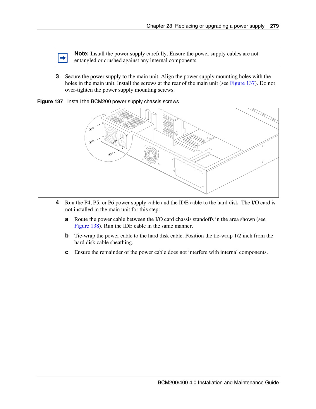
Install the BCM200 power supply chassis screws
Power supply
Fan
Hard disk
Install the BCM200 MSC guide bracket
Power supply LED
Removing a BCM400 standard power supply
Remove the BCM400 power supply screws
To remove a BCM400 standard power supply
To install a BCM400 standard power supply
Installing a BCM400 standard power supply
Fasten the power supply support bracket cables
Fasten the standard power supply to the main unit
Upgrading to a redundant power supply
Redundant power supply upgrade overview
Removing the PSU status connector jumper
Installing a redundant power supply cage BCM400 only
To remove the PSU status connector jumper
To install a redundant power supply cage BCM400 only
Remove the power supply knockout bracket
Attach the redundant power supply cage
Install a new cable clamp
To remove a BCM400 redundant power supply cage
Removing a BCM400 redundant power supply cage
Remove the BCM400 redundant power supply screws
To install a power supply module
Installing a power supply module
Install the power supply modules into the power supply cage
To remove a power supply module
Removing a power supply module
Remove the power supply module from the power supply cage
Replacing cards
Replacing data cards and processing hardware
Base function tray interior components
Replacing data cards and processing hardware
To remove the WAN card
Card replacement overview
Remove the WAN card and PCI cover plate
Installing the WAN card
Install the WAN card
To install a replacement WAN card
To remove the media services card MSC
MSC mounting screws
To install the media services card MSC
To remove the modem card
Modem card positioning
Modem card pin locking clip
To install a modem card
Installing the modem card
Modem port label
Provides an overview of the process for replacing a PEC
Replacing the processor expansion card PEC
PEC replacement overview
To remove the processor expansion card PEC
Remove the processor expansion card PEC
Installing a processor expansion card PEC
Replacing memory
To install a PEC
Removing the dual in-line memory module Dimm card
Increasing the amount of memory
To remove a Dimm card
Base function
Tray front
To install a Dimm card
Replacing the clock/calendar battery
Battery replacement overview
To remove the clock/calendar battery
Base function tray front
Removing the clock/calendar battery
To install a new clock/calendar battery
Replacing data cards and processing hardware N0060612
Replacing or installing a cooling fan
Replacing or installing a cooling fan
Replacing a cooling fan
To remove a BCM400 cooling fan
Removing a BCM400 cooling fan
Remove the BCM400 fan access panel
To install a BCM400 cooling fan
Installing a BCM400 cooling fan
Fan chassis mounting holes
Connect the fan cables to the I/O card
Install the fan access panel to the main unit
To remove a BCM200 cooling fan
Removing a BCM200 cooling fan
Disconnect the BCM200 fan cable from the I/O card
To install a BCM200 cooling fan
Installing the BCM200 cooling fan
To remove an expansion unit fan
Removing an expansion unit fan
FAN
Troubleshooting cooling fans
Fan and temperature LEDs on the base function tray
LED Label Description Green LED On Red LED On Only
DTM wiring chart
Appendix a DTM wiring chart
DTM RJ-48C port wiring
Appendix a DTM wiring chart N0060612
Pin Signal Signal on system side
Brim wiring chart
Appendix B Brim wiring chart
Brim RJ-45 port wiring
Appendix B Brim wiring chart N0060612
Line Pin Connection Wire color
Gatm wiring chart
Appendix C Gatm wiring chart
GATM4 RJ-21 connector wiring Sheet 1
GATM8 RJ-21 connector wiring Sheet 1
Ring Slate-Violet
Appendix C Gatm wiring chart N0060612
4x16
4x16 wiring charts
Appendix D 4x16 wiring charts
4x16 RJ-11 port wiring
Set Pin Connection Wire color
4x16 MBM RJ-21 connector wiring Sheet 1
No connection Violet-Slate Slate-Violet
Appendix D 4x16 wiring charts N0060612
DSM16 and DSM32 wiring charts
Appendix E DSM16 and DSM32 wiring charts
DSM16 and DSM32 RJ-21 connector wiring Sheet 1
N0060612
ASM8, ASM8+, and GASM8 wiring chart
Appendix F ASM8, ASM8+, and GASM8 wiring chart
ASM RJ-21 connector wiring Sheet 1
No connection Violet-Slate Slate-Violet
Market profile attributes
Media bay module availability
Media bay module availability by market profile Sheet 1
FEM MBM-Norstar trunk cartridge combinations
Analog trunk card
Canada Caribbean Denmark
Time and date format based on language
Time zones and language information
South/Central America language support
Language support for South America and Central America
Appendix G Market profile attributes
Time/date formats based on language
Core parameters for market profiles
Caller ID display formats
Market profile Functionality Attribute Australia Brazil
N0060612
BCM200/400 4.0 Installation and Maintenance Guide
Vicap
PBX
N0060612
PRC
Mcdn 4ESS
BCM200/400 4.0 Installation and Maintenance Guide
Vicap
ITU-T
N0060612
Vicap
Pulse Dialing ms
Global analog trunk parameters
Transmission parameters
Busy tone Reversal
On-hook caller ID Disconnect supervision Message waiting
Market Start Digit Line Voltage Stutter Profile
Stop Digit
GASM8 parameters
Transmission
Input
EIA/TIA-464A
Dial pulse
Dial pulse and Dtmf parameters
Protocol Market profile Available Isdn services
Isdn line services
Isdn line services
Isdn services by protocol
Analog and digital trunk types
Analog and digital trunk types and descriptions Sheet 1
Trunk types Description Digital trunk types
Analog trunk types
Trunk types Description
Numbers
Index
CTM
Index
Isdn
MBM
PCI
WAN