Signal type | Function |
|
|
|
|
|
|
| |
Control signal | Controls camera functions (pan/tilt, zooming, focusing, lens iris, preset position) and camera | ||||||||
| site accessories. |
|
|
|
|
|
|
| |
|
|
|
|
|
|
|
|
|
|
Status signal | Shows camera status. |
|
|
|
|
|
|
| |
|
|
|
|
|
|
|
|
|
|
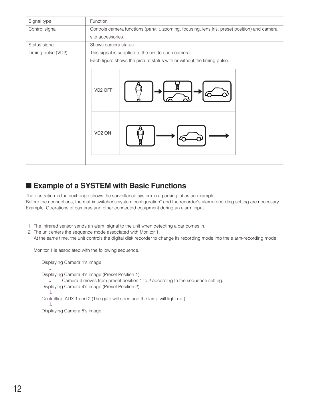
Timing pulse (VD2) | This signal is supplied to the unit to each camera. |
|
| ||||||
| Each figure shows the picture status with or without the timing pulse. | ||||||||
|
|
|
|
|
|
|
|
|
|
|
| VD2 OFF | s |
|
| s | |||
|
|
|
|
|
| ||||
|
|
|
|
|
| ||||
VD2 ON
s ![]() s
s
■Example of a SYSTEM with Basic Functions
The illustration in the next page shows the surveillance system in a parking lot as an example.
Before the connections, the matrix switcher's system configuration* and the recorder's alarm recording setting are necessary. Example: Operations of cameras and other connected equipment during an alarm input
1.The infrared sensor sends an alarm signal to the unit when detecting a car comes in.
2.The unit enters the sequence mode associated with Monitor 1.
At the same time, the unit controls the digital disk recorder to change its recording mode into the
Monitor 1 is associated with the following sequence.
Displaying Camera 1's image
↓
Displaying Camera 4's image (Preset Position 1)
↓Camera 4 moves from preset position 1 to 2 according to the sequence setting.
Displaying Camera 4's image (Preset Position 2)
↓
Controlling AUX 1 and 2 (The gate will open and the lamp will light up.)
↓
Displaying Camera 5's image
12
