■System Status Table
The current system status can be identified.
The continuous display becomes possible by the OSD set- ting.
|
| SYSTEM STATUS |
|
| |
MON | CAM | MODE | KB | OPE | PRI |
1 | 01 | T01 | K1 | 12345 | 30 |
2 | 99 | SPOT | K2 | 2 | 2 |
3 | 04 | ALARM | K4 | 4 | 1 |
4 | R1 | RECORDER | PC | 30 | 1 |
MON: Monitor number
CAM: Camera number / Recorder number
MODE: Operation mode
KB: Controller name
OPE: Operator number
PRI: Priority
■Setup Procedures
To use the unit, it is necessary to configure the system through the following setup procedures:
•OSD setup with an active monitor and system controller The basic parameters are configurable to operate the unit.
•
The setup utility can configure all the functions of the unit.
Refer to p. 63
■Extended Functions
If a recorder is connected to the matrix switcher, the follow- ing will be available.
●Recorder Connection
The operations are conducted with the buttons on the recorder, system controller or PC.
•The setup of the recording device
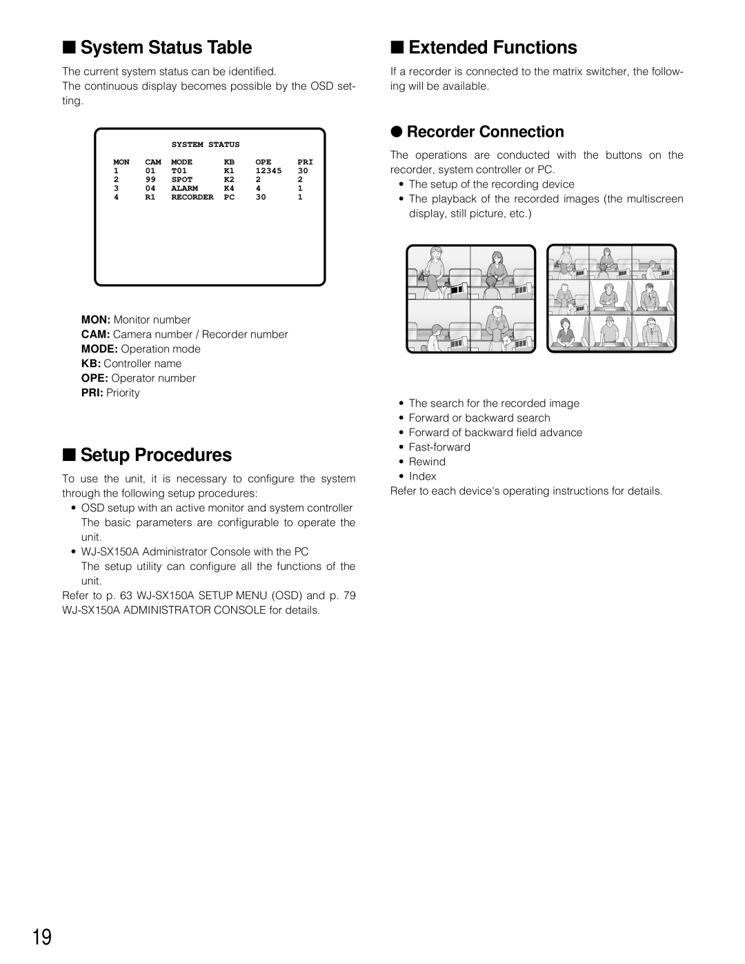
•The playback of the recorded images (the multiscreen display, still picture, etc.)
•The search for the recorded image
•Forward or backward search
•Forward of backward field advance
•
•Rewind
•Index
Refer to each device's operating instructions for details.
19