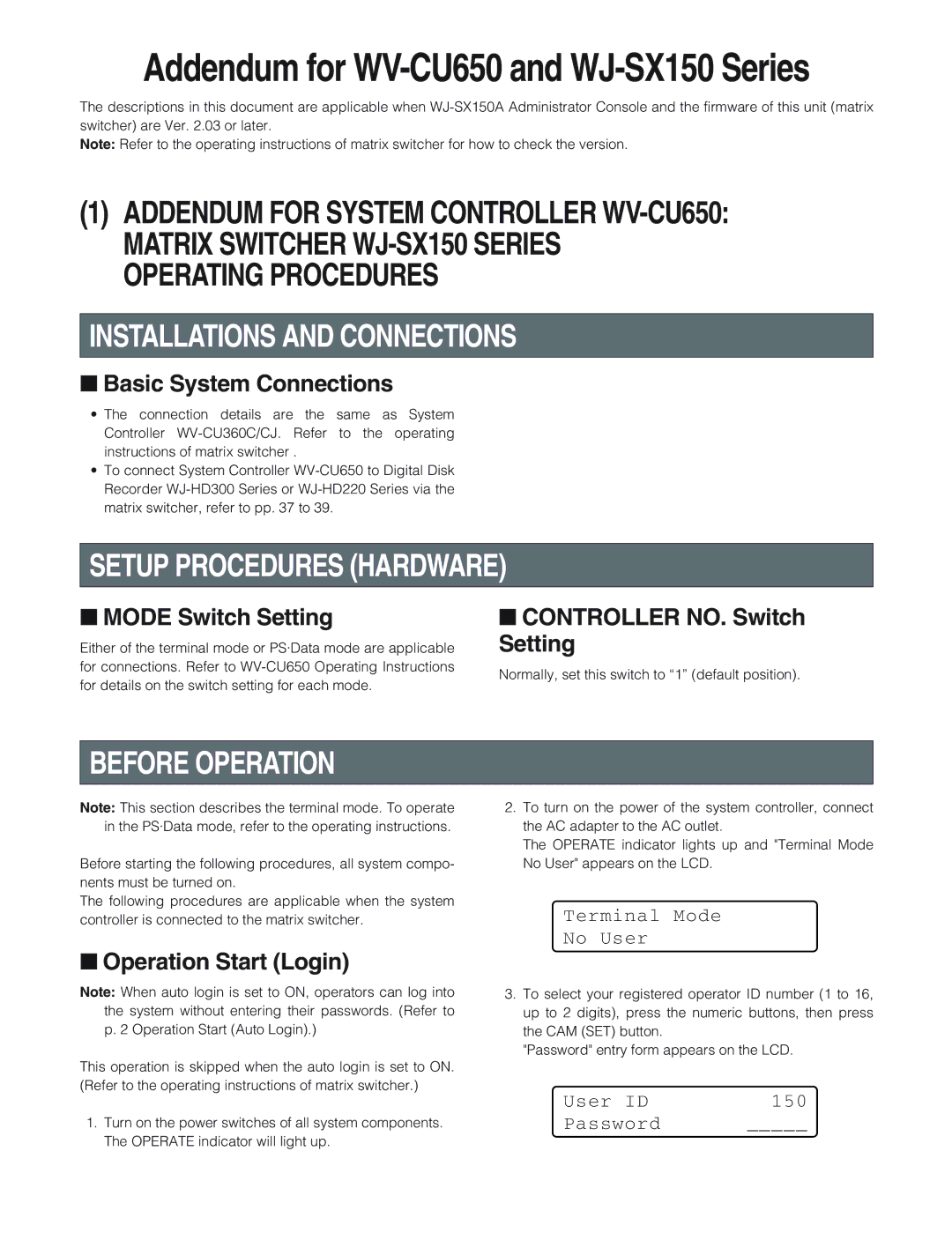
Addendum for WV-CU650 and WJ-SX150 Series
The descriptions in this document are applicable when
Note: Refer to the operating instructions of matrix switcher for how to check the version.
(1)ADDENDUM FOR SYSTEM CONTROLLER
INSTALLATIONS AND CONNECTIONS
■Basic System Connections
•The connection details are the same as System Controller
•To connect System Controller
SETUP PROCEDURES (HARDWARE)
■MODE Switch Setting
Either of the terminal mode or PS·Data mode are applicable for connections. Refer to
■CONTROLLER NO. Switch Setting
Normally, set this switch to “1” (default position).
BEFORE OPERATION
Note: This section describes the terminal mode. To operate in the PS·Data mode, refer to the operating instructions.
Before starting the following procedures, all system compo- nents must be turned on.
The following procedures are applicable when the system controller is connected to the matrix switcher.
■Operation Start (Login)
Note: When auto login is set to ON, operators can log into the system without entering their passwords. (Refer to p. 2 Operation Start (Auto Login).)
This operation is skipped when the auto login is set to ON. (Refer to the operating instructions of matrix switcher.)
1.Turn on the power switches of all system components. The OPERATE indicator will light up.
2.To turn on the power of the system controller, connect the AC adapter to the AC outlet.
The OPERATE indicator lights up and "Terminal Mode No User" appears on the LCD.
Terminal Mode
No User
3.To select your registered operator ID number (1 to 16, up to 2 digits), press the numeric buttons, then press the CAM (SET) button.
"Password" entry form appears on the LCD.
User ID | 150 |
Password | _____ |
