• RS485 CAMERA
This menu links to the submenu.
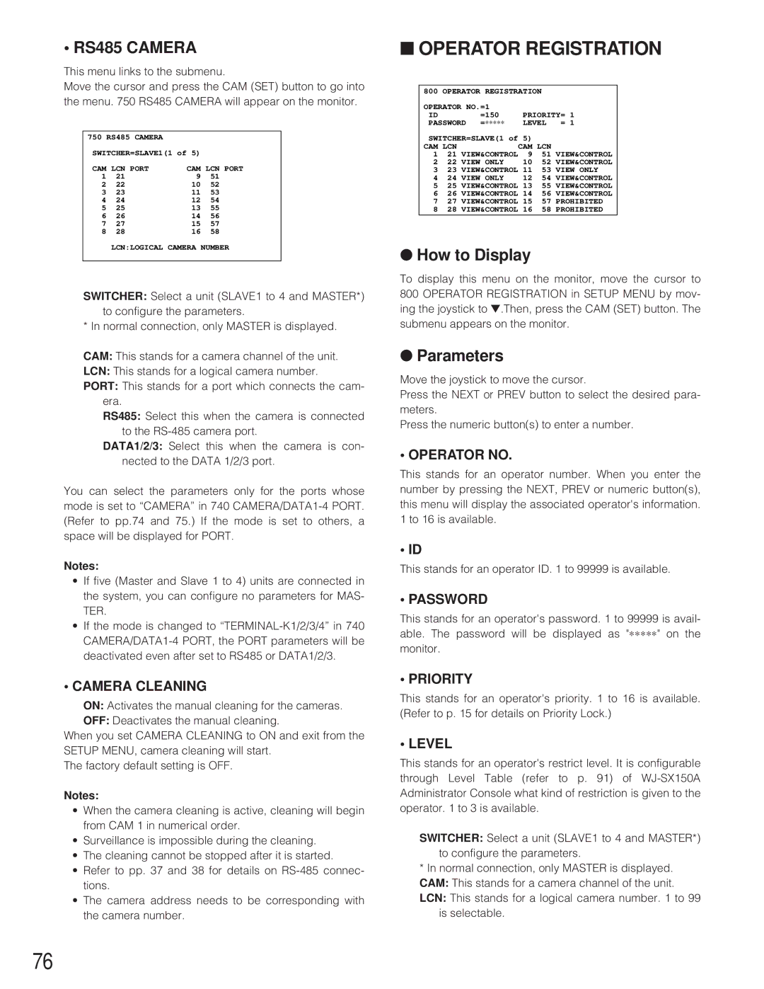
Move the cursor and press the CAM (SET) button to go into the menu. 750 RS485 CAMERA will appear on the monitor.
750 RS485 CAMERA |
|
| |
SWITCHER=SLAVE1(1 of 5) |
| ||
CAM LCN PORT | CAM LCN PORT | ||
1 | 21 | 9 | 51 |
2 | 22 | 10 | 52 |
3 | 23 | 11 | 53 |
4 | 24 | 12 | 54 |
5 | 25 | 13 | 55 |
6 | 26 | 14 | 56 |
7 | 27 | 15 | 57 |
8 | 28 | 16 | 58 |
LCN:LOGICAL CAMERA NUMBER
SWITCHER: Select a unit (SLAVE1 to 4 and MASTER*) to configure the parameters.
* In normal connection, only MASTER is displayed.
CAM: This stands for a camera channel of the unit.
LCN: This stands for a logical camera number.
PORT: This stands for a port which connects the cam- era.
RS485: Select this when the camera is connected to the
DATA1/2/3: Select this when the camera is con- nected to the DATA 1/2/3 port.
You can select the parameters only for the ports whose mode is set to “CAMERA” in 740
Notes:
•If five (Master and Slave 1 to 4) units are connected in the system, you can configure no parameters for MAS- TER.
•If the mode is changed to
•CAMERA CLEANING
ON: Activates the manual cleaning for the cameras.
OFF: Deactivates the manual cleaning.
When you set CAMERA CLEANING to ON and exit from the SETUP MENU, camera cleaning will start.
The factory default setting is OFF.
Notes:
•When the camera cleaning is active, cleaning will begin from CAM 1 in numerical order.
•Surveillance is impossible during the cleaning.
•The cleaning cannot be stopped after it is started.
•Refer to pp. 37 and 38 for details on
•The camera address needs to be corresponding with the camera number.
■OPERATOR REGISTRATION
800 | OPERATOR REGISTRATION |
|
| ||
OPERATOR NO.=1 |
|
|
| ||
ID |
| =150 | PRIORITY= 1 | ||
PASSWORD =∗∗∗∗∗ | LEVEL | = 1 | |||
SWITCHER=SLAVE(1 of | 5) |
|
| ||
CAM | LCN |
| CAM LCN |
| |
1 | 21 | VIEW&CONTROL | 9 | 51 | VIEW&CONTROL |
2 | 22 | VIEW ONLY | 10 | 52 | VIEW&CONTROL |
3 | 23 | VIEW&CONTROL | 11 | 53 | VIEW ONLY |
4 | 24 | VIEW ONLY | 12 | 54 | VIEW&CONTROL |
525 VIEW&CONTROL 13 55 VIEW&CONTROL
626 VIEW&CONTROL 14 56 VIEW&CONTROL
727 VIEW&CONTROL 15 57 PROHIBITED
828 VIEW&CONTROL 16 58 PROHIBITED
●How to Display
To display this menu on the monitor, move the cursor to 800 OPERATOR REGISTRATION in SETUP MENU by mov- ing the joystick to ▼.Then, press the CAM (SET) button. The submenu appears on the monitor.
●Parameters
Move the joystick to move the cursor.
Press the NEXT or PREV button to select the desired para- meters.
Press the numeric button(s) to enter a number.
• OPERATOR NO.
This stands for an operator number. When you enter the number by pressing the NEXT, PREV or numeric button(s), this menu will display the associated operator's information. 1 to 16 is available.
• ID
This stands for an operator ID. 1 to 99999 is available.
• PASSWORD
This stands for an operator's password. 1 to 99999 is avail- able. The password will be displayed as "∗∗∗∗∗ " on the
monitor.
• PRIORITY
This stands for an operator's priority. 1 to 16 is available. (Refer to p. 15 for details on Priority Lock.)
• LEVEL
This stands for an operator's restrict level. It is configurable through Level Table (refer to p. 91) of
SWITCHER: Select a unit (SLAVE1 to 4 and MASTER*) to configure the parameters.
*In normal connection, only MASTER is displayed. CAM: This stands for a camera channel of the unit. LCN: This stands for a logical camera number. 1 to 99
is selectable.
76
