(2)ADDENDUM FOR MATRIX SWITCHER
WJ-HD300 SERIES/WJ-HD220 SERIES
SYSTEM CONNECTIONS AND SETUPS
■Connection with Digital Disk Recorder WJ-HD300 Series
Notes:
•Refer to service personnel for details on the connection with a recorder to operate via LAN or the Internet.
•Check that the firmware of recorder is Ver. 1.30 or later.
•Only one recorder can be connected to the DATA HDR connector of this unit. (Multiple unit connections, such as cascade connection, are not available.)
●Basic Connection
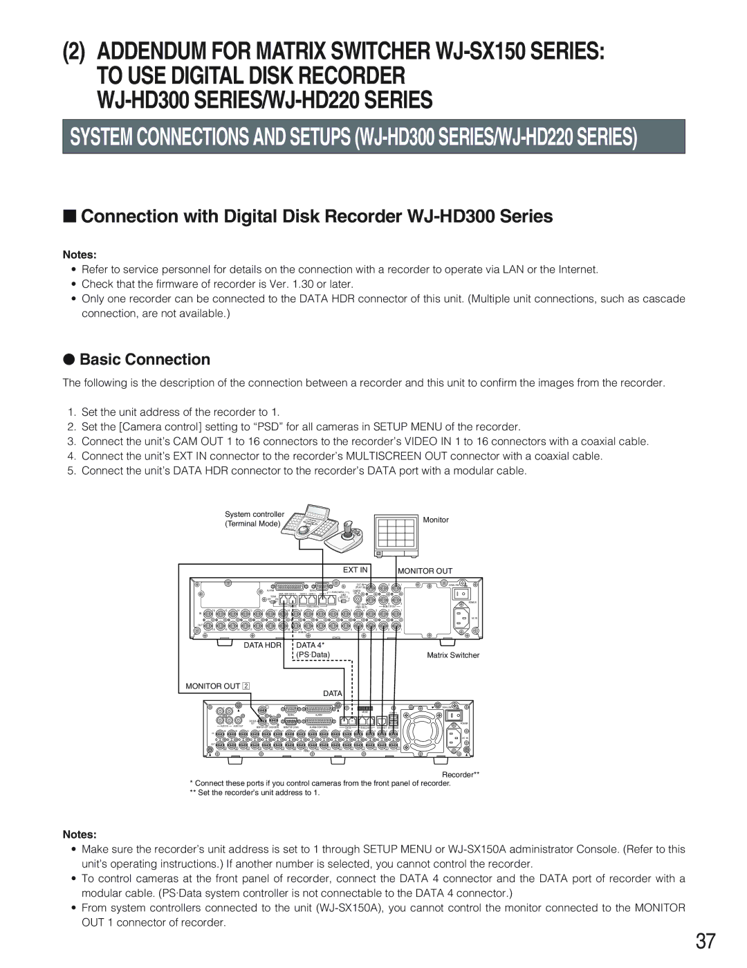
The following is the description of the connection between a recorder and this unit to confirm the images from the recorder.
1.Set the unit address of the recorder to 1.
2.Set the [Camera control] setting to “PSD” for all cameras in SETUP MENU of the recorder.
3.Connect the unit’s CAM OUT 1 to 16 connectors to the recorder’s VIDEO IN 1 to 16 connectors with a coaxial cable.
4.Connect the unit’s EXT IN connector to the recorder’s MULTISCREEN OUT connector with a coaxial cable.
5.Connect the unit’s DATA HDR connector to the recorder’s DATA port with a modular cable.
| System controller |
|
|
|
|
|
|
|
|
|
|
| Monitor | ||||
| (Terminal Mode) |
|
|
|
|
|
|
|
|
|
|
| |||||
|
|
|
|
|
|
|
|
|
|
|
|
| |||||
|
|
|
|
|
|
|
|
|
|
| EXT IN |
|
| MONITOR OUT | |||
|
|
|
|
|
|
|
|
|
|
|
|
| EXT IN |
| 3 | 1 | SIGNAL GND |
|
|
|
| ALARM |
|
|
| SERIAL |
|
|
|
| (PLAY IN) |
|
|
|
|
|
|
|
| DATA HDR DATA 4 | DATA 3 | DATA 1 | RS485(CAMERA) |
| CAMERA |
|
|
|
| ||||
|
|
|
|
| DATA 2 |
| LINE |
| SW IN |
|
|
|
| ||||
|
|
|
| TERM |
|
|
|
| 2 | SELECT | 4 |
|
|
|
|
| |
|
|
|
| OFF | ON |
|
|
|
|
|
|
|
|
|
| ||
|
|
|
|
|
|
|
|
|
|
|
|
| EXT OUT |
| 4 | 2 | POWER |
|
|
|
|
|
|
|
|
|
|
|
|
|
|
| |||
|
|
|
|
|
| PS•DATA | RS485(CAMERA) |
|
|
|
| (REC OUT) |
| MONITOR OUT |
|
| |
16 | 15 | 14 | 13 | 12 | 11 | 10 | 9 | 8 | 7 | 6 |
| 5 | 4 | 3 | 2 | 1 |
|
IN |
|
|
|
|
|
|
|
|
|
|
|
|
|
|
|
|
|
|
|
|
|
|
|
|
|
|
|
|
|
|
|
|
|
| AC IN |
OUT |
|
|
|
|
|
|
|
|
|
|
|
|
|
|
|
|
|
16 | 15 | 14 | 13 | 12 | 11 | 10 | 9 | 8 | 7 | 6 |
| 5 | 4 | 3 | 2 | 1 |
|
|
|
|
|
|
|
| CAMERA |
|
|
|
|
|
|
|
|
|
|
|
|
| DATA HDR |
| DATA 4* |
|
|
|
|
|
|
|
| ||||
|
|
|
|
|
|
| (PS·Data) |
|
|
|
|
|
|
| Matrix Switcher | ||
MONITOR OUT x
DATA
3 | 1 |
| 1 |
|
|
|
|
|
| SERIAL | ALARM |
|
| CASCADE |
|
|
|
4 | 2 | OUT | 2 |
|
|
AUDIO IN | AUDIO OUT |
| MONITOR OUT CASCADE IN | MONITOR (VGA) | ALARM/CONTOROL |
|
|
| SIGNAL GND |
| MODE |
| COPY 1 |
| 2 | 1 |
|
|
|
| POWER |
DATA | RS485(CAMERA) | ||
16 | 15 | 14 | 13 | 12 | 11 | 10 | 9 | 8 | 7 | 6 | 5 | 4 | 3 | 2 | 1 |
IN |
|
|
|
|
|
|
|
|
|
|
|
|
|
|
|
|
|
|
|
|
|
|
|
|
|
|
|
|
|
| AC IN |
OUT |
|
|
|
|
|
|
|
|
|
|
|
|
|
|
|
16 | 15 | 14 | 13 | 12 | 11 | 10 | 9 | 8 | 7 | 6 | 5 | 4 | 3 | 2 | 1 |
|
|
|
|
|
|
| VIDEO |
|
|
|
|
|
|
|
|
Recorder**
*Connect these ports if you control cameras from the front panel of recorder.
**Set the recorder’s unit address to 1.
Notes:
•Make sure the recorder’s unit address is set to 1 through SETUP MENU or
•To control cameras at the front panel of recorder, connect the DATA 4 connector and the DATA port of recorder with a modular cable. (PS·Data system controller is not connectable to the DATA 4 connector.)
•From system controllers connected to the unit
37
