■Connection with Digital Disk Recorder WJ-HD100 Series
MUX
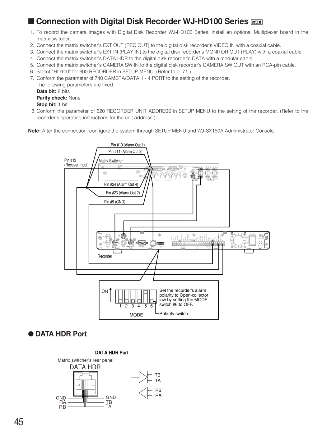
1.To record the camera images with Digital Disk Recorder
2.Connect the matrix switcher’s EXT OUT (REC OUT) to the digital disk recorder’s VIDEO IN with a coaxial cable.
3.Connect the matrix switcher’s EXT IN (PLAY IN) to the digital disk recorder’s MONITOR OUT (PLAY) with a coaxial cable.
4.Connect the matrix switcher’s DATA HDR to the digital disk recorder’s DATA with a modular cable.
5.Connect the matrix switcher’s CAMERA SW IN to the digital disk recorder’s CAMERA SW OUT with an
6.Select “HD100” for 600 RECORDER in SETUP MENU. (Refer to p. 71.)
7.Conform the parameter of 740 CAMERA/DATA 1 - 4 PORT to the setting of the recorder. The following parameters are fixed.
Data bit: 8 bits
Parity check: None
Stop bit: 1 bit
8Conform the parameter of 620 RECORDER UNIT ADDRESS in SETUP MENU to the setting of the recorder. (Refer to the recorder’s operating instructions for the unit address.)
Note: After the connection, configure the system through SETUP MENU and
Pin #10 (Alarm Out 1)
Pin #11 (Alarm Out 3)
Pin #13 | Matrix Switcher |
(Recover Input) |
|
|
|
|
|
| EXT IN | 3 | 1 |
ALARM |
| SERIAL |
|
| (PLAY IN) |
|
|
| RS485(CAMERA) | CAMERA |
|
| |||
| DATA HDR DATA 4 | DATA 3 DATA 2 DATA 1 | SW IN |
|
| ||
|
| LINE |
|
| |||
TERM |
|
|
|
|
| ||
| 2 | SELECT | 4 |
|
| ||
OFF | ON |
|
|
|
| ||
|
|
|
|
| EXT OUT | 4 | 2 |
| PS•DATA | RS485(CAMERA) |
|
| (REC OUT) | MONITOR OUT |
|
Pin #24 (Alarm Out 4)
Pin #23 (Alarm Out 2)
Pin #9 (GND)
IN |
| IN |
|
| REC)(EXT | PLAY REC G OUT IN OUTPLAY | OUTREC OFFAUTOOUT ENDDISKOUT OUT IN | G RECALL | OUT RECOVEROUT INRESET IN | |
OUT |
| OUT |
|
|
|
|
|
|
|
|
AUDIO | CAMERA | VIDEO MONITOR OUT | DATA | MODE | REMOTE | TIME | SERIES |
| ALARM | |
SW OUT |
| |||||||||
|
| (PLAY) |
|
|
|
| ADJUST | RECORD |
|
|
Recorder
ON |
|
|
|
|
|
|
|
|
|
|
|
|
|
|
|
| Set the recorder’s alarm |
|
|
|
|
|
|
|
|
|
|
|
|
|
|
|
| ||
|
|
|
|
|
|
|
|
|
|
|
|
|
|
|
|
| polarity to |
|
|
|
|
|
|
|
|
|
|
|
|
|
|
|
|
| |
|
|
|
|
|
|
|
|
|
|
|
|
|
|
|
|
| low by setting the MODE |
|
|
|
|
|
|
|
|
|
|
|
|
|
|
|
|
| |
1 | 2 | 3 | 4 |
| 5 | 6 |
|
|
| switch #6 to OFF. | |||||||
|
|
|
|
| |||||||||||||
|
|
|
|
|
| MODE |
|
|
|
|
|
| Polarity switch | ||||
|
|
|
|
|
|
|
|
|
|
|
| ||||||
|
|
|
|
|
|
|
|
|
|
|
|
| |||||
POWER
ON
SIGNAL GND
OFF
●DATA HDR Port
DATA HDR Port
Matrix switcher's rear panel
DATA HDR
GND
RA
RB
TB
TA
RB
GNDRA
TB
TA
45