• CAM 01 to 16:
These stand for an operator's camera operation coverage. The following are the parameters.
VIEW & CONTROL: The operator can display the cam- era image on the monitor and control panning/tilt- ing.
VIEW ONLY: The operator can display the camera image on the monitor, but cannot control the pan- ning/tilting.
PROHIBITED: The operator can neither display the camera image on the monitor nor control the pan- ning/tilting.
The following is the factory default setting of this menu.
OPERATOR NO. | ID | PASSWORD | LEVEL | PRIORITY |
1 | 150 | 150 | 1 | 1 |
2 | 1 | 12345 | 1 | 2 |
3 | 100 | 100 | 1 | 3 |
4 | 101 | 101 | 1 | 4 |
5 | 102 | 102 | 2 | 5 |
6 | 103 | 103 | 3 | 6 |
CAM 1 to 16 = VIEW & CONTROL (for OPERATOR NO. 1 to 6)
Note: When you enter an invalid number, the parameter will return to the state before your numerical entry.
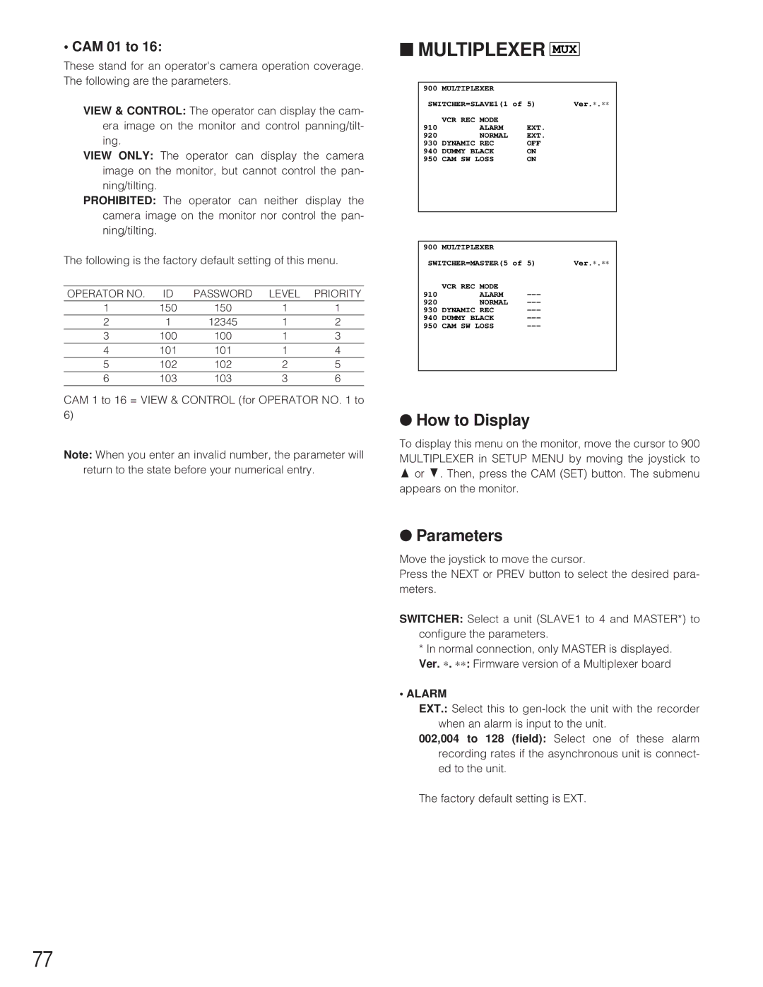
■MULTIPLEXER MUX
900 | MULTIPLEXER |
|
|
SWITCHER=SLAVE1(1 of 5) | Ver.∗ .∗∗ | ||
| VCR REC MODE |
|
|
910 | ALARM | EXT. |
|
920 | NORMAL | EXT. |
|
930 | DYNAMIC REC | OFF |
|
940 | DUMMY BLACK | ON |
|
950 | CAM SW LOSS | ON |
|
|
|
|
|
|
|
|
|
900 | MULTIPLEXER |
|
|
SWITCHER=MASTER(5 of 5) | Ver.∗ .∗∗ | ||
| VCR REC MODE |
|
|
910 | ALARM |
| |
920 | NORMAL |
| |
930 | DYNAMIC REC |
| |
940 | DUMMY BLACK |
| |
950 | CAM SW LOSS |
| |
|
|
|
|
●How to Display
To display this menu on the monitor, move the cursor to 900 MULTIPLEXER in SETUP MENU by moving the joystick to D or C. Then, press the CAM (SET) button. The submenu appears on the monitor.
●Parameters
Move the joystick to move the cursor.
Press the NEXT or PREV button to select the desired para- meters.
SWITCHER: Select a unit (SLAVE1 to 4 and MASTER*) to configure the parameters.
*In normal connection, only MASTER is displayed. Ver. ∗ . ∗∗ : Firmware version of a Multiplexer board
•ALARM
EXT.: Select this to
002,004 to 128 (field): Select one of these alarm recording rates if the asynchronous unit is connect- ed to the unit.
The factory default setting is EXT.
77