4GENERAL SET
5 Turn the shuttle dial clockwise and turn the jog dial to set “ALARM INFO”, and then turn the shuttle dial clockwise.
The cursor moves to “ADDRESS”.
SET> | ||
DATA SPEED | : | 19200 |
STATUS INFO | : | ON |
ALARM INFO | : | ON |
ADDRESS | : | 000 |
[Settings] ( indicates default setting)
Setting | Description |
|
|
ON | Alarm information is transmitted. |
|
|
OFF | Alarm information is not transmitted. |
|
|
6 Turn the shuttle dial clockwise and set “ADDRESS” with the jog dial or numeric keys and then turn the shuttle dial clockwise.
SET> | ||
|
|
|
DATA SPEED | : | 19200 |
STATUS INFO | : | ON |
ALARM INFO | : | ON |
ADDRESS | : | 001 |
[Setting conditions]
Addresses between “0” and “127” can be set for this unit.
7 Press the [EXIT/OSD] button.
The setting procedure is ended and the display returns to the normal screen.
EXIT/OSD
Setting camera control
The following procedure explains settings and operations of remote controllable cameras connected to the VIDEO IN terminals via coaxial cable.
1 Press the [MENU] button, turn the jog dial to select “3. GENERAL SET” and then turn the shuttle dial clockwise.
The <GENERAL SET> screen is displayed.
MENU
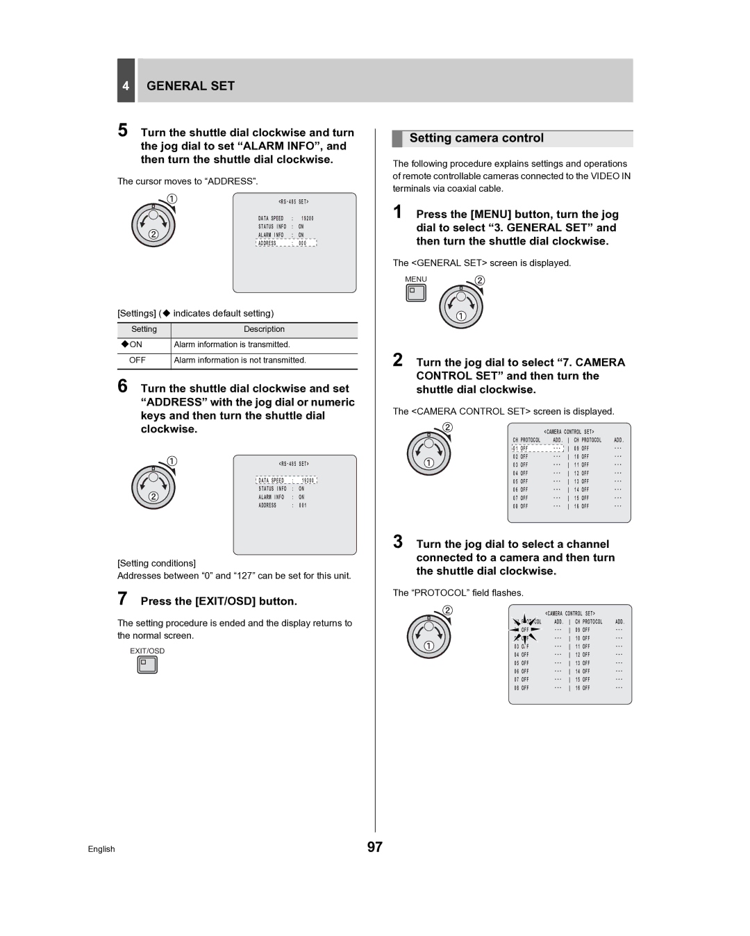
2 Turn the jog dial to select “7. CAMERA CONTROL SET” and then turn the shuttle dial clockwise.
The <CAMERA CONTROL SET> screen is displayed.
|
| <CAMERA CONTROL SET> |
| |||
CH PROTOCOL | ADD. | CH PROTOCOL | ADD. | |||
01 | OFF | 09 | OFF | |||
02 | OFF | 10 | OFF | |||
03 | OFF | 11 | OFF | |||
04 | OFF | 12 | OFF | |||
05 | OFF | 13 | OFF | |||
06 | OFF | 14 | OFF | |||
07 | OFF | 15 | OFF | |||
08 | OFF | 16 | OFF | |||
3 Turn the jog dial to select a channel connected to a camera and then turn the shuttle dial clockwise.
The “PROTOCOL” field flashes.
|
| <CAMERA CONTROL SET> |
| |||
| PROTOCOL | ADD. | CH PROTOCOL | ADD. | ||
| OFF | 09 | OFF | |||
| OFF | 10 | OFF | |||
03 |
| 11 | OFF | |||
04 | OFF | 12 | OFF | |||
05 | OFF | 13 | OFF | |||
06 | OFF | 14 | OFF | |||
07 | OFF | 15 | OFF | |||
08 | OFF | 16 | OFF | |||
English | 97 |