4GENERAL SET
Making network settings
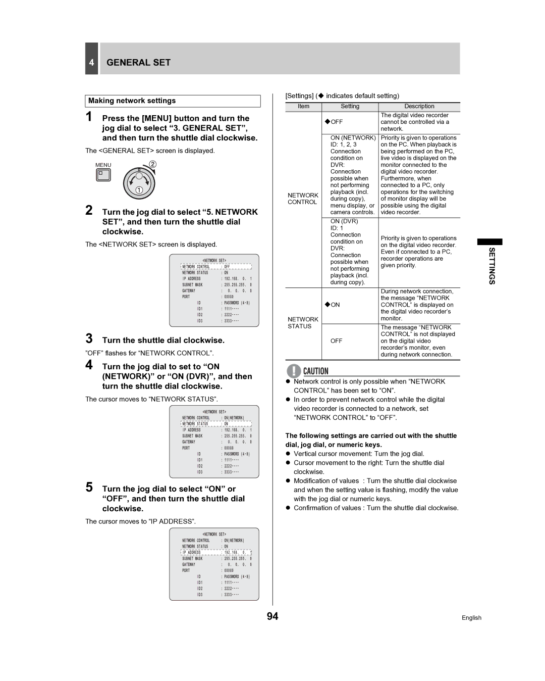
1 Press the [MENU] button and turn the jog dial to select “3. GENERAL SET”, and then turn the shuttle dial clockwise.
The <GENERAL SET> screen is displayed.
MENU
2 Turn the jog dial to select “5. NETWORK
SET”, and then turn the shuttle dial clockwise.
The <NETWORK SET> screen is displayed.
<NETWORK SET> |
|
| |
NETWORK CONTROL | : OFF |
|
|
NETWORK STATUS | : ON |
|
|
IP ADDRESS | : 192.168. | 0. | 1 |
SUBNET MASK | : 255.255.255. | 0 | |
GATEWAY | : 0. 0. | 0. | 0 |
PORT | : 00080 |
|
|
ID | : PASSWORD | ||
ID1 | : |
|
|
ID2 | : |
|
|
ID3 | : |
|
|
3 Turn the shuttle dial clockwise.
”OFF” flashes for “NETWORK CONTROL”.
4 Turn the jog dial to set to “ON (NETWORK)” or “ON (DVR)”, and then turn the shuttle dial clockwise.
The cursor moves to “NETWORK STATUS”.
<NETWORK SET> |
|
| |
NETWORK CONTROL | : ON(NETWORK) |
| |
NETWORK STATUS | : ON |
|
|
IP ADDRESS | : 192.168. | 0. | 1 |
SUBNET MASK | : 255.255.255. | 0 | |
GATEWAY | : 0. 0. | 0. | 0 |
PORT | : 00080 |
|
|
ID | : PASSWORD | ||
ID1 | : |
|
|
ID2 | : |
|
|
ID3 | : |
|
|
5 Turn the jog dial to select “ON” or “OFF”, and then turn the shuttle dial clockwise.
The cursor moves to “IP ADDRESS”.
<NETWORK SET> |
|
| |
NETWORK CONTROL | : ON(NETWORK) |
| |
NETWORK STATUS | : ON |
|
|
|
|
|
|
IP ADDRESS | : 192.168. | 0. | 1 |
SUBNET MASK | : 255.255.255. | 0 | |
GATEWAY | : 0. 0. | 0. | 0 |
PORT | : 00080 |
|
|
ID | : PASSWORD | ||
ID1 | : |
|
|
ID2 | : |
|
|
ID3 | : |
|
|
[Settings] ( indicates default setting)
Item | Setting | Description |
|
|
| OFF | The digital video recorder |
|
|
| cannot be controlled via a |
| ||
|
| network. |
| |
| ON (NETWORK) | Priority is given to operations |
| |
| ID: 1, 2, 3 | on the PC. When playback is |
| |
| Connection | being performed on the PC, |
| |
| condition on | live video is displayed on the |
| |
| DVR: | monitor connected to the |
| |
| Connection | digital video recorder. |
| |
| possible when | Furthermore, when |
| |
| not performing | connected to a PC, only |
| |
NETWORK | playback (incl. | operations for the switching |
| |
during copy), | of monitor display will be |
| ||
CONTROL |
| |||
menu display, or | possible using the digital |
| ||
|
| |||
| camera controls. | video recorder. |
| |
| ON (DVR) |
|
|
|
| ID: 1 |
|
|
|
| Connection | Priority is given to operations |
| |
| condition on |
| ||
| on the digital video recorder. |
| ||
| DVR: | SETTINGS | ||
| Even if connected to a PC, | |||
| during copy). | |||
| Connection | recorder operations are |
| |
| possible when | given priority. |
| |
| not performing |
| ||
|
|
|
| |
| playback (incl. |
|
|
|
|
| During network connection, |
| |
| ON | the message “NETWORK |
| |
| CONTROL” is displayed on |
| ||
|
| the digital video recorder’s |
| |
NETWORK |
| monitor. |
| |
STATUS |
| The message “NETWORK |
| |
|
| CONTROL” is not displayed |
| |
| OFF | on the digital video |
| |
|
| recorder’s monitor, even |
| |
|
| during network connection. |
| |
zNetwork control is only possible when “NETWORK CONTROL” has been set to “ON”.
zIn order to prevent network control while the digital video recorder is connected to a network, set “NETWORK CONTROL” to “OFF”.
The following settings are carried out with the shuttle dial, jog dial, or numeric keys.
zVertical cursor movement: Turn the jog dial.
zCursor movement to the right: Turn the shuttle dial clockwise.
zModification of values : Turn the shuttle dial clockwise and when the setting value is flashing, modify the value with the jog dial or numeric keys.
zConfirmation of values : Turn the shuttle dial clockwise.
94 | English |
