3INSTALLATION AND CONNECTIONS
Connection
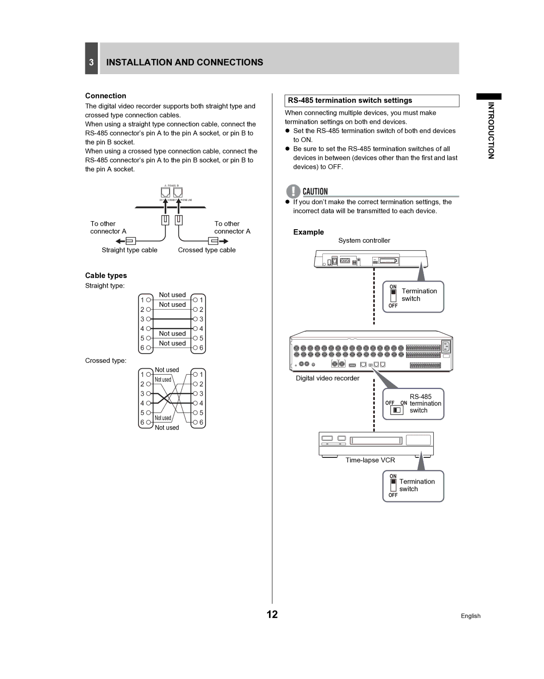
The digital video recorder supports both straight type and crossed type connection cables.
When using a straight type connection cable, connect the
When using a crossed type connection cable, connect the
| A RS485 B |
DO | CONNECT PHONE LINE |
To other |
|
|
|
|
|
|
|
|
|
|
|
|
| To other | ||||||||
|
|
|
|
|
|
|
|
|
|
|
| |||||||||||
|
|
|
|
|
| |||||||||||||||||
connector A |
|
|
|
|
|
|
| connector A | ||||||||||||||
|
|
|
|
|
|
|
|
|
|
|
|
|
|
|
|
|
|
|
|
| ||
Straight type cable |
| Crossed type cable | ||||||||||||||||||||
Cable types
Straight type: |
|
| |
1 | Not used | 1 | |
Not used | |||
2 | 2 | ||
| |||
3 |
| 3 | |
4 | Not used | 4 | |
5 | 5 | ||
Not used | |||
6 | 6 | ||
| |||
Crossed type: |
|
| |
1 | Not used | 1 | |
Not used | |||
2 | 2 | ||
| |||
3 |
| 3 | |
4 |
| 4 |
RS-485 termination switch settings
When connecting multiple devices, you must make termination settings on both end devices.
zSet the
zBe sure to set the
zIf you don’t make the correct termination settings, the incorrect data will be transmitted to each device.
Example
System controller
ON Termination switch
OFF
Digital video recorder
OFF ON termination
INTRODUCTION
5 | Not used | 5 | |
6 | 6 | ||
Not used | |||
|
|
ON
switch
Termination switch
OFF
12 | English |
