4GENERAL SET
4 Following this, turn the shuttle dial clockwise.
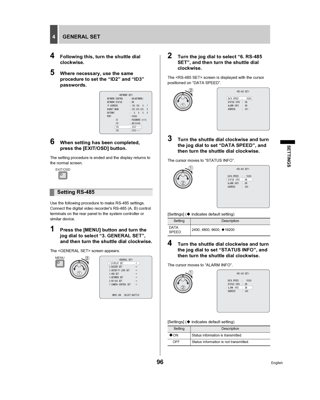
5 Where necessary, use the same procedure to set the “ID2” and “ID3” passwords.
| <NETWORK SET> |
|
| |
NETWORK CONTROL | : ON(NETWORK) |
| ||
NETWORK STATUS | : ON |
|
| |
IP ADDRESS | : 192.168. | 0. | 1 | |
SUBNET MASK | : 255.255.255. | 0 | ||
GATEWAY | : 0. 0. | 0. | 0 | |
PORT | : 00080 |
|
| |
| ID | : PASSWORD | ||
| ID1 | : AB123456 |
|
|
|
|
|
|
|
| ID2 | : |
|
|
| ID3 | : |
|
|
6 When setting has been completed, press the [EXIT/OSD] button.
The setting procedure is ended and the display returns to the normal screen.
EXIT/OSD
Setting RS-485
Use the following procedure to make
1 Press the [MENU] button and turn the jog dial to select “3. GENERAL SET”, and then turn the shuttle dial clockwise.
The <GENERAL SET> screen appears.
MENU |
| |
| <GENERAL SET> |
|
| 1.DISPLAY SET | |
| 2.BUZZER SET | |
| 3.SECURITY LOCK SET | |
| 4.HDD SET | |
| 5.NETWORK SET | |
| ||
| 7.CAMERA CONTROL SET | |
MOVE:JOG SELECT:SHUTTLE
2 Turn the jog dial to select “6.
The
SET> | ||
|
|
|
DATA SPEED | : | 19200 |
STATUS INFO | : | ON |
ALARM INFO | : | ON |
ADDRESS | : | 001 |
3 Turn the shuttle dial clockwise and turn the jog dial to set “DATA SPEED”, and then turn the shuttle dial clockwise.
The cursor moves to “STATUS INFO”.
SET> | ||
DATA SPEED | : | 19200 |
STATUS INFO | : | ON |
ALARM INFO | : | ON |
ADDRESS | : | 000 |
[Settings] ( indicates default setting)
Setting | Description | |
|
| |
DATA | 2400, 4800, 9600, 19200 | |
SPEED | ||
| ||
|
|
4 Turn the shuttle dial clockwise and turn the jog dial to set “STATUS INFO”, and then turn the shuttle dial clockwise.
The cursor moves to “ALARM INFO”.
SET> | ||
DATA SPEED | : | 19200 |
STATUS INFO | : | ON |
ALARM INFO | : | ON |
ADDRESS | : | 000 |
[Settings] ( indicates default setting)
Setting | Description |
|
|
ON | Status information is transmitted. |
|
|
OFF | Status information is not transmitted. |
|
|
SETTINGS
96 | English |