3INSTALLATION AND CONNECTIONS
This section describes how to connect the digital video recorder to video cameras and other devices. Be sure to read the instruction manuals for each connected device.
zImproper connections can result in malfunction or the emission of smoke.
zA separate power supply is required for operation of each camera.
Basic connections
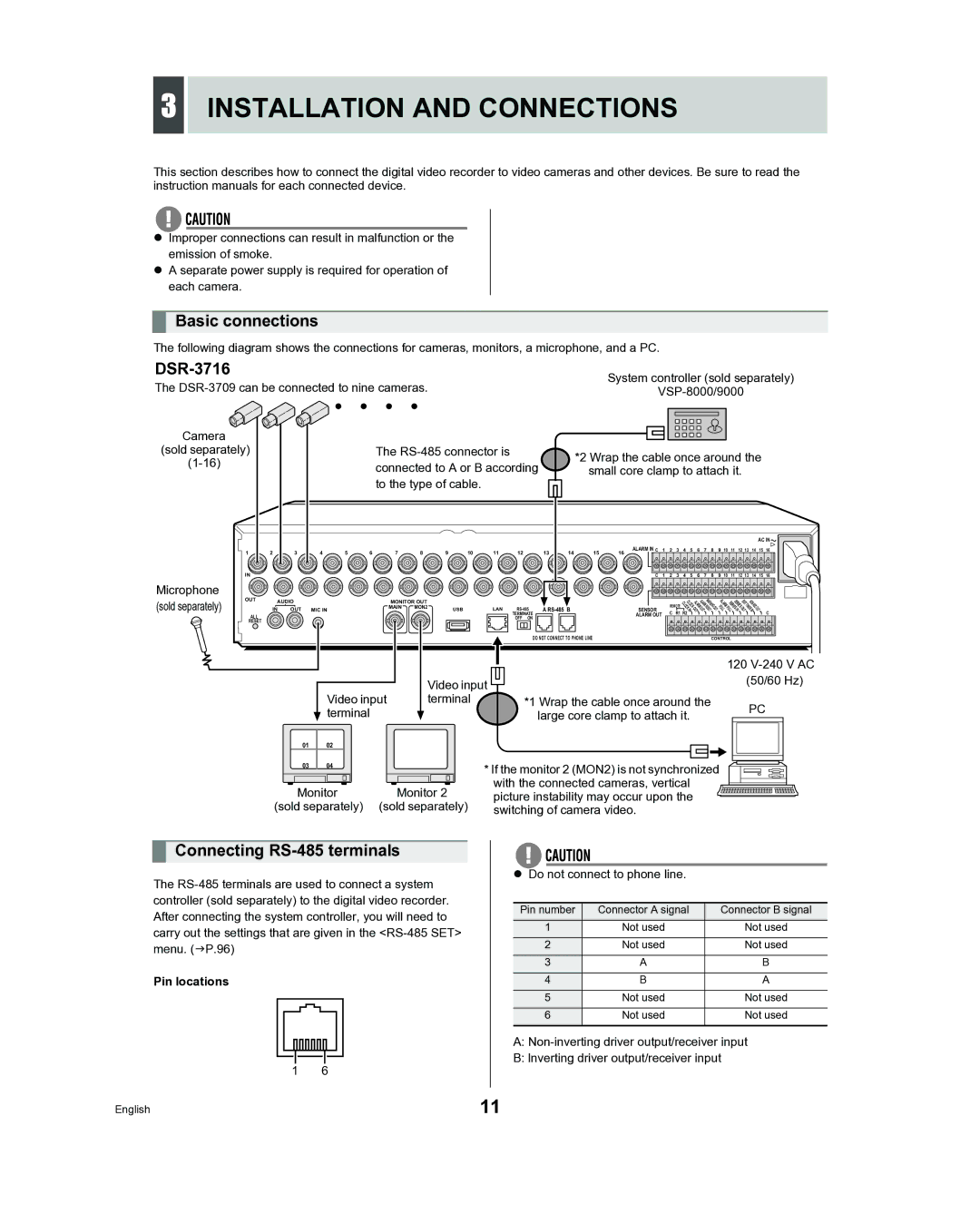
The following diagram shows the connections for cameras, monitors, a microphone, and a PC.
DSR-3716
The
Camera |
|
(sold separately) | The |
connected to A or B according | |
| |
| to the type of cable. |
System controller (sold separately)
*2 Wrap the cable once around the small core clamp to attach it.
Microphone (sold separately)
1 | 2 | 3 | 4 | 5 | 6 | 7 | 8 | 9 | 10 | 11 | 12 |
IN |
|
|
|
|
|
|
|
|
|
|
|
OUT | AUDIO |
|
|
| MONITOR OUT |
|
|
|
| ||
|
|
|
|
|
|
|
| ||||
| IN | OUT | MIC IN |
|
| MAIN | MON2 |
| USB | LAN | |
|
|
|
|
|
| ||||||
ALL |
|
|
|
|
|
|
|
|
|
| TERMINATE |
|
|
|
|
|
|
|
|
|
| OFF ON | |
RESET |
|
|
|
|
|
|
|
|
|
|
|
|
|
|
|
|
|
|
|
|
|
|
|
|
|
|
|
|
|
|
| AC IN | |
13 | 14 | 15 | ALARM IN C | 1 | 2 | 3 | 4 | 5 | 6 | 7 | 8 | 9 | 10 | 11 | 12 13 | 14 | 15 | 16 | |||
16 |
|
|
|
|
|
|
|
|
|
|
|
|
|
|
|
|
|
| |||
|
|
| C | 1 | 2 | 3 | 4 | 5 | 6 | 7 | 8 | 9 | 10 | 11 | 12 | 13 | 14 | 15 | 16 | ||
|
|
|
|
|
|
|
|
|
| ALARMWARNING | ALARM |
|
| E | NO |
|
| ||||
|
|
|
|
|
|
| CLOC |
| SERIESSERIES |
| REC |
| |||||||||
|
|
|
|
| REMOTECLOC | K RM | RE |
| F |
|
|
| |||||||||
|
|
|
|
|
|
|
|
| ALA |
|
|
|
|
|
|
| XIT | N |
|
| |
|
|
|
|
|
|
| K |
|
| OUT | S | OU U |
|
|
| OUTIMER O |
| ||||
A |
| SENSOR |
|
|
| I OU | ET |
| T LLFULL IN | T | I | U |
| ||||||||
|
|
|
| N | T |
|
|
|
|
|
|
| N | T |
| ||||||
|
|
| ALARM OUT |
| C | R1 R2 |
|
|
|
|
|
|
|
|
|
|
|
|
| C | |
|
|
|
|
|
|
|
|
|
|
|
|
|
|
|
|
|
|
|
|
| |
DO NOT CONNECT TO PHONE LINE | CONTROL |
|
|
|
|
|
|
| Video input |
|
|
|
|
|
|
| ||
|
|
|
|
|
|
|
|
|
|
|
|
|
| |||
|
|
|
|
|
|
|
|
|
|
|
|
|
| |||
|
|
| Video input | terminal |
|
|
|
| *1 Wrap the cable once around the | |||||||
|
|
| terminal |
|
|
|
|
|
| large core clamp to attach it. | ||||||
01 |
|
|
|
|
|
|
|
|
|
|
|
|
|
| ||
02 |
|
|
|
|
|
|
|
|
|
|
|
|
| |||
|
|
|
|
|
|
|
|
|
|
|
|
|
|
|
|
|
|
|
|
|
|
|
|
|
|
|
|
|
|
|
|
|
|
03 | 04 |
|
|
|
|
| * If the monitor 2 (MON2) is not synchronized | |||||||||
|
|
|
|
|
|
|
|
|
| with the connected cameras, vertical | ||||||
|
| Monitor | Monitor 2 |
| ||||||||||||
|
|
| picture instability may occur upon the | |||||||||||||
(sold separately) (sold separately) |
| switching of camera video. | ||||||||||||||
120
(50/60 Hz)
PC
Connecting RS-485 terminals
The
Pin locations
1 6
zDo not connect to phone line.
Pin number | Connector A signal | Connector B signal |
1 | Not used | Not used |
2 | Not used | Not used |
3 | A | B |
4 | B | A |
5 | Not used | Not used |
6 | Not used | Not used |
|
|
|
A:
B:lnverting driver output/receiver input
English | 11 |