Installing the Spray ECU | V1.98 21/06/06 |
|
|
1.1 INSTALLING THE SPRAY ECU (ALL MODELS)
Step 1: Installing the Spray ECU 30S
Note: DISCONNECT THE VEHICLE BATTERY before proceeding with any installation or servicing of the Spray ECU 30S or Tractor harness. Before commencing any installation or servicing of the Sprayer Harness or Valve Harness, make sure the Tractor Harness is disconnected from the Sprayer harness. DAMAGE WILL OCCUR if any external power is applied to the Section Drive Outputs on the Spray ECU.
ALWAYS DISCONNECT THE VEHICLE BATTERY before proceeding with any welding, jump starting or charging on the vehicle or sprayer.
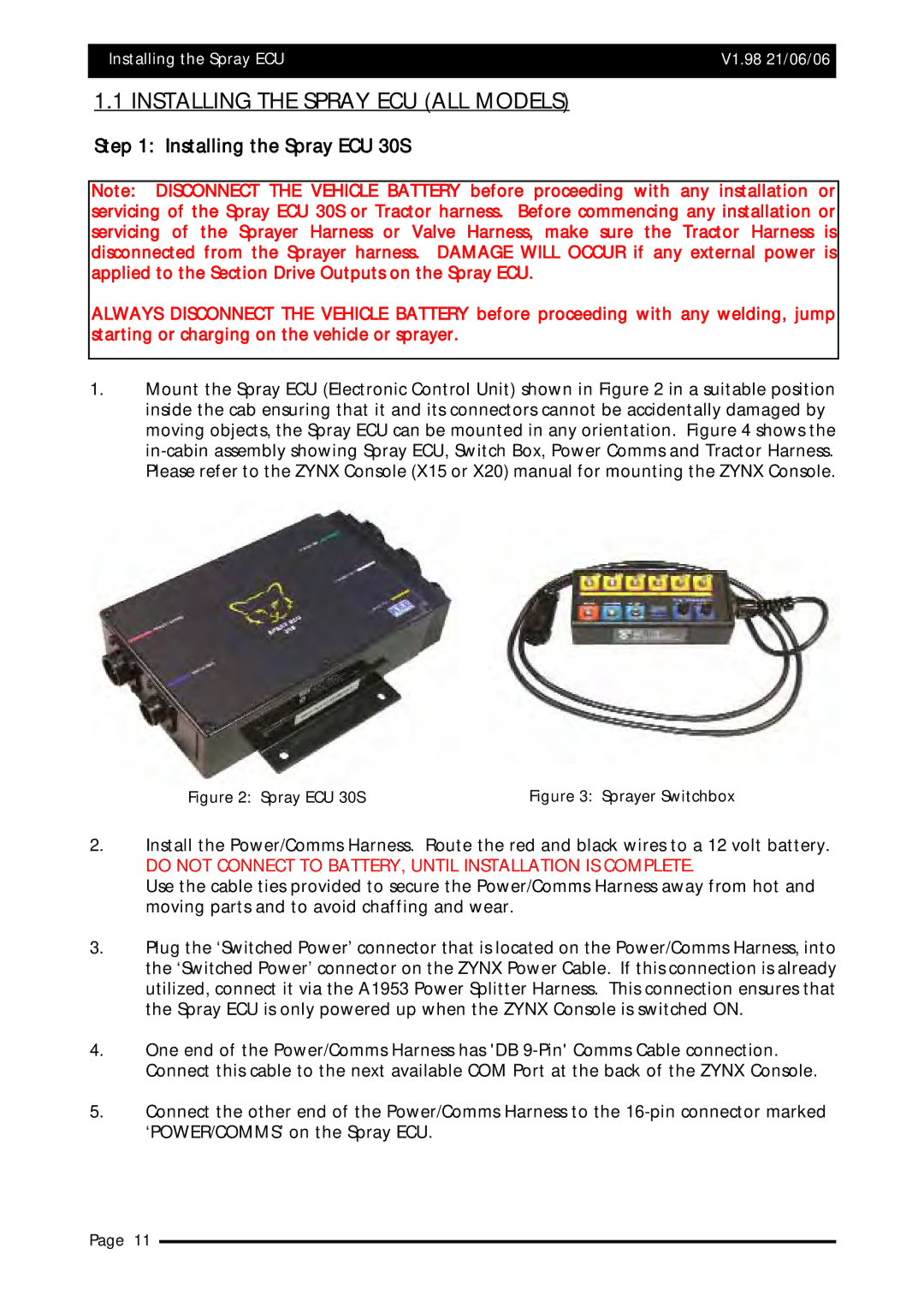
1.Mount the Spray ECU (Electronic Control Unit) shown in Figure 2 in a suitable position inside the cab ensuring that it and its connectors cannot be accidentally damaged by moving objects, the Spray ECU can be mounted in any orientation. Figure 4 shows the
Figure 2: Spray ECU 30S | Figure 3: Sprayer Switchbox |
2.Install the Power/Comms Harness. Route the red and black wires to a 12 volt battery.
DO NOT CONNECT TO BATTERY, UNTIL INSTALLATION IS COMPLETE.
Use the cable ties provided to secure the Power/Comms Harness away from hot and moving parts and to avoid chaffing and wear.
3.Plug the ‘Switched Power’ connector that is located on the Power/Comms Harness, into the ‘Switched Power’ connector on the ZYNX Power Cable. If this connection is already utilized, connect it via the A1953 Power Splitter Harness. This connection ensures that the Spray ECU is only powered up when the ZYNX Console is switched ON.
4.One end of the Power/Comms Harness has 'DB
5.Connect the other end of the Power/Comms Harness to the
Page 11