Setup Options- Switches | V1.98 21/06/06 |
|
|
8.1SWITCHES (Spray ECU Only)
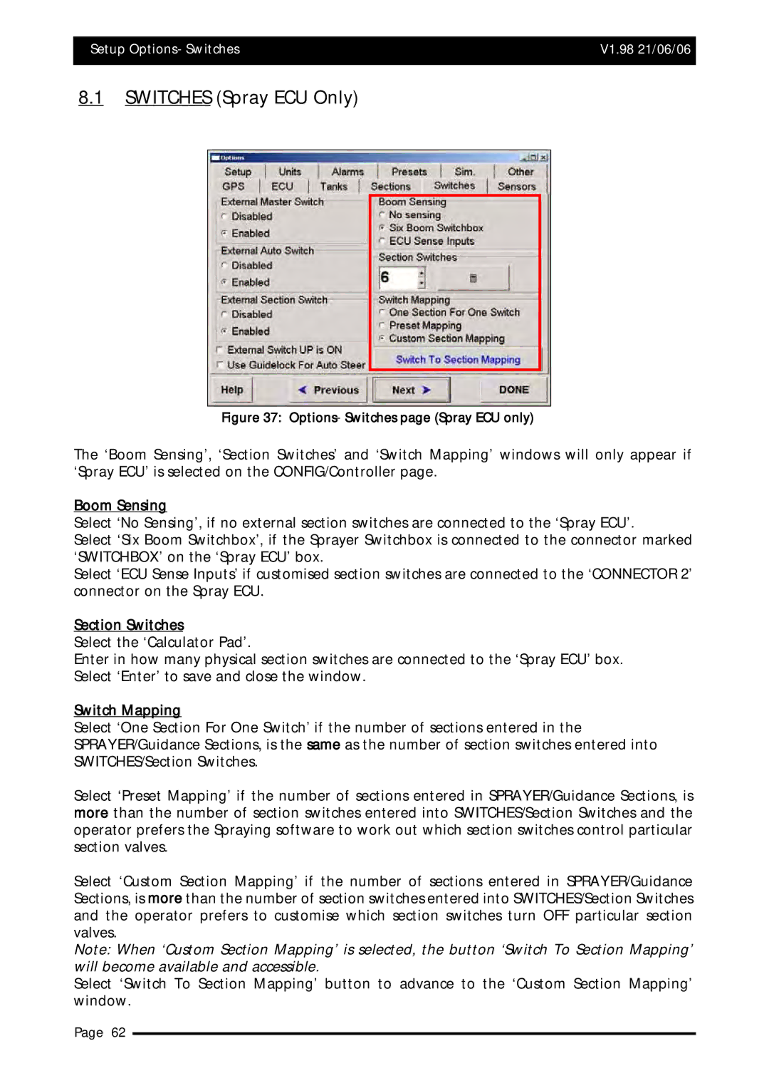
Figure 37: Options- Switches page (Spray ECU only)
The ‘Boom Sensing’, ‘Section Switches’ and ‘Switch Mapping’ windows will only appear if ‘Spray ECU’ is selected on the CONFIG/Controller page.
Boom Sensing
Select ‘No Sensing’, if no external section switches are connected to the ‘Spray ECU’.
Select ‘Six Boom Switchbox’, if the Sprayer Switchbox is connected to the connector marked ‘SWITCHBOX’ on the ‘Spray ECU’ box.
Select ‘ECU Sense Inputs’ if customised section switches are connected to the ‘CONNECTOR 2’ connector on the Spray ECU.
Section Switches
Select the ‘Calculator Pad’.
Enter in how many physical section switches are connected to the ‘Spray ECU’ box. Select ‘Enter’ to save and close the window.
Switch Mapping
Select ‘One Section For One Switch’ if the number of sections entered in the SPRAYER/Guidance Sections, is the same as the number of section switches entered into SWITCHES/Section Switches.
Select ‘Preset Mapping’ if the number of sections entered in SPRAYER/Guidance Sections, is more than the number of section switches entered into SWITCHES/Section Switches and the operator prefers the Spraying software to work out which section switches control particular section valves.
Select ‘Custom Section Mapping’ if the number of sections entered in SPRAYER/Guidance Sections, is more than the number of section switches entered into SWITCHES/Section Switches and the operator prefers to customise which section switches turn OFF particular section valves.
Note: When ‘Custom Section Mapping’ is selected, the button ‘Switch To Section Mapping’ will become available and accessible.
Select ‘Switch To Section Mapping’ button to advance to the ‘Custom Section Mapping’ window.
Page 62
