Testing | V1.98 21/06/06 |
|
|
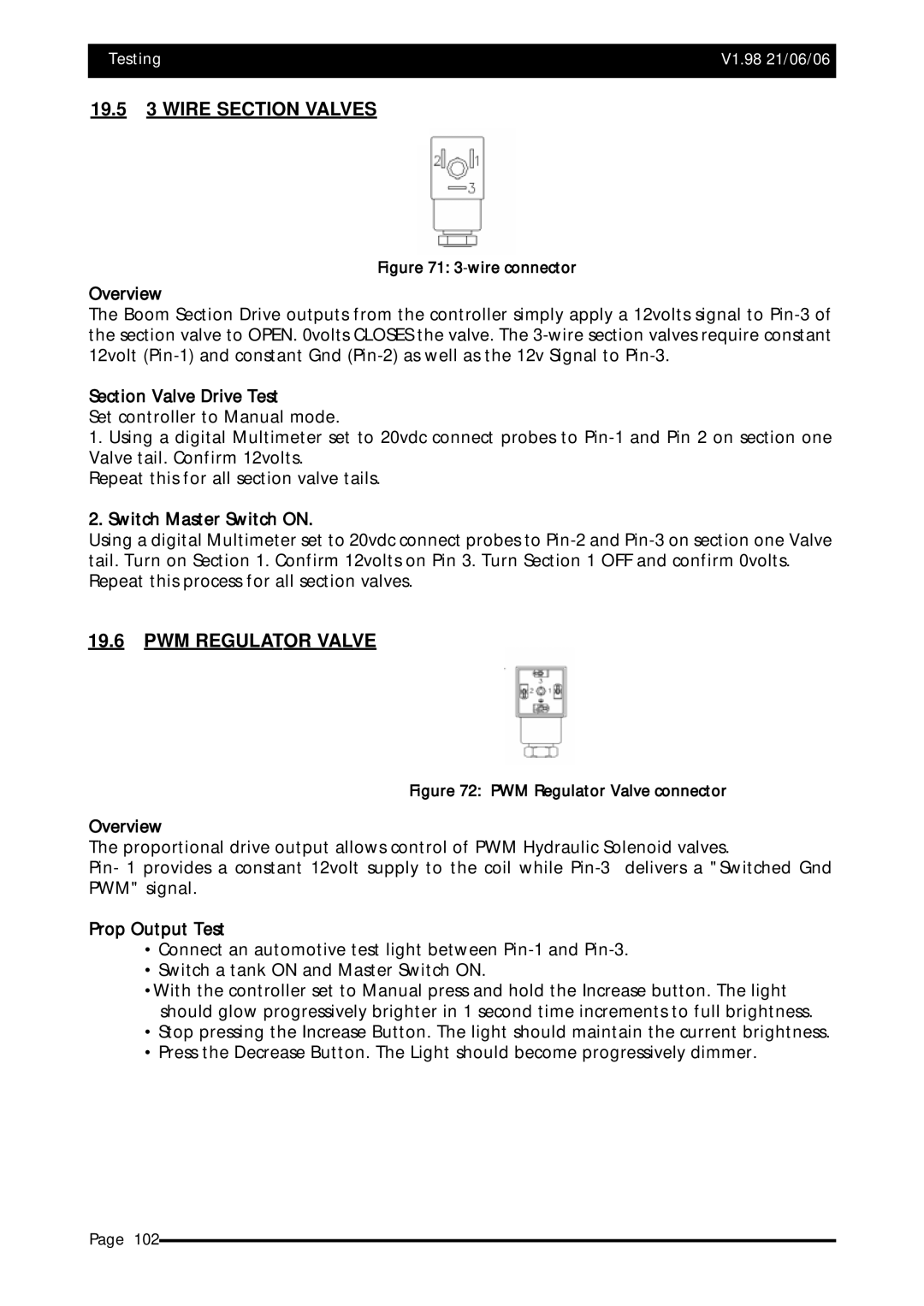
19.53 WIRE SECTION VALVES
Figure 71: 3-wire connector
Overview
The Boom Section Drive outputs from the controller simply apply a 12volts signal to
Section Valve Drive Test
Set controller to Manual mode.
1.Using a digital Multimeter set to 20vdc connect probes to
Repeat this for all section valve tails.
2.Switch Master Switch ON.
Using a digital Multimeter set to 20vdc connect probes to
19.6PWM REGULATOR VALVE
Figure 72: PWM Regulator Valve connector
Overview
The proportional drive output allows control of PWM Hydraulic Solenoid valves.
Pin- 1 provides a constant 12volt supply to the coil while
Prop Output Test
•Connect an automotive test light between
•Switch a tank ON and Master Switch ON.
•With the controller set to Manual press and hold the Increase button. The light should glow progressively brighter in 1 second time increments to full brightness.
•Stop pressing the Increase Button. The light should maintain the current brightness.
•Press the Decrease Button. The Light should become progressively dimmer.
Page 102