Manuals
/
Topcom
/
Power Tools
/
Paint Sprayer
Topcom
X20
manual
Alarm Defaults, Zynx Sprayer Alarms Defaults
Models:
X20
1
74
172
172
Download
172 pages
56.91 Kb
71
72
73
74
75
76
77
78
Page 74
Image 74
Setup Options
-Alarms
V1.98 21/06/06
Major Topic Heading
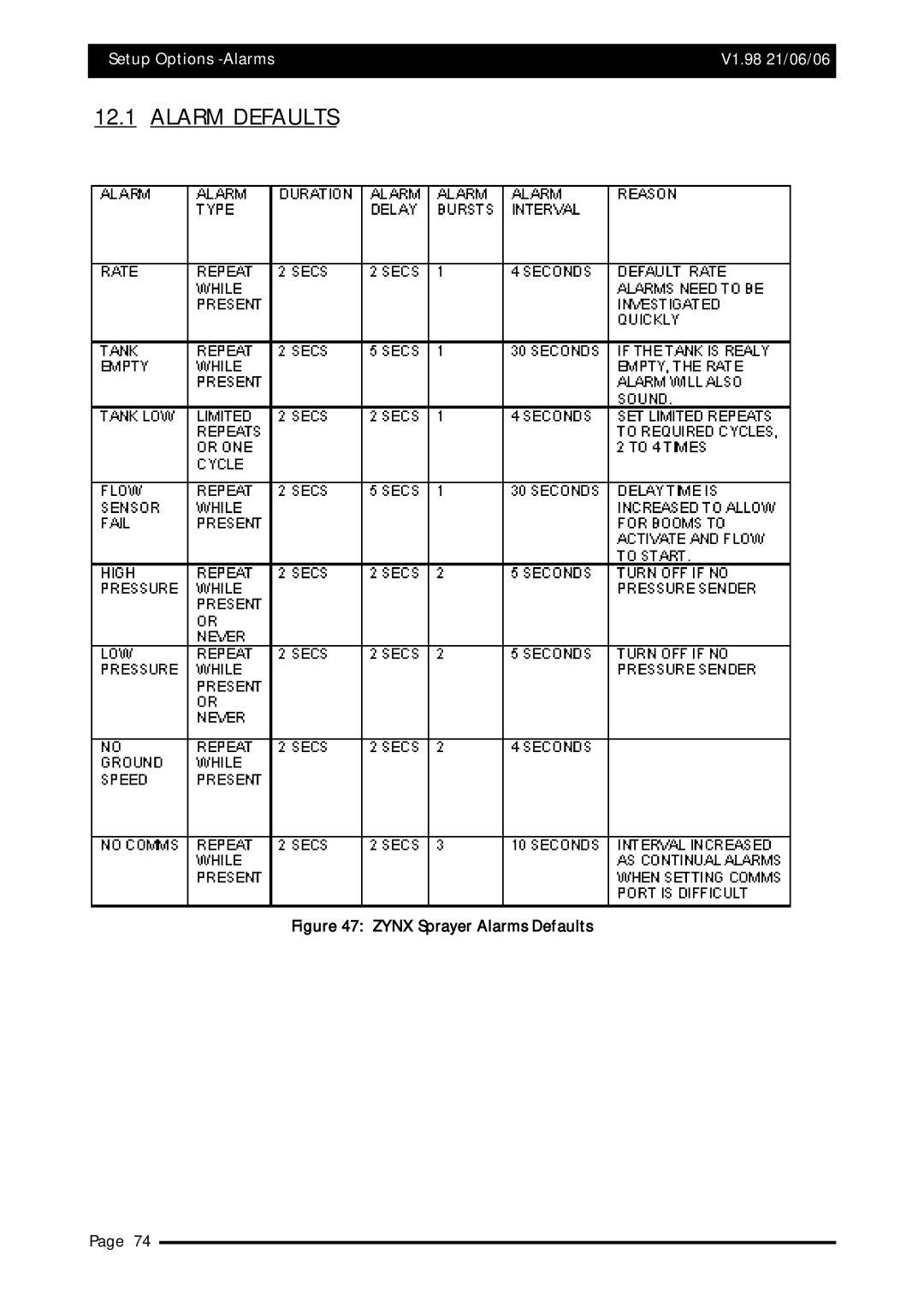
12.1 ALARM DEFAULTS
Figure 47: ZYNX Sprayer Alarms Defaults
Page 74
Page 73
Page 75
Page 74
Image 74
Page 73
Page 75
Contents
Spray Rate Control
ABC
Sprayer Setup Options
Start Spraying
Wiring Connection Tables
Introduction
HOW to USE this Manual
How to use this Manual V1.98 21/06/06
Spray Rate Control
For ALL Installations and Servicing of Spray Ecus
Installing the Spray ECU ALL Models
Installing the Spray ECU 30S
Installing the Spray ECU V1.98 21/06/06
Installation of Spray ECU 30S KEE Sprayer Kits
Installing the Tractor Harness
General Incab assembly
General Sprayer and Valve harness assembly
Installing the Sprayer Harness
Connecting to a Speed Sensor
Shaft/Sensor with Mounting Bracket
Installation of a Shaft/Speed Sensor kit to a tail shaft
Using an existing radar speed sensor for ground speed
Connecting to Flow Meter
Connecting to the Regulator Valve
Pressure Sensor installation and connection
Installing the Valve Harness
Connecting to the Dump Valve
Single Line Install
Dual Line Install
Explanation of the Different types of Valves
Plumbing for Diaphragm Pumps for KEE Sprayer Kits
Plumbing Diaphragm Pumps for KEE Sprayer kits
Plumbing for Centrifugal Pumps for KEE Sprayer Kits
Plumbing for Centrifical Pumps for KEE Sprayer kits
Installing Spray ECU 30S Kits to AN Existing KEE Controller
Page
Switches on Existing Controller
Digital Multimeter DMM Test Procedure
Page
Connecting the Spray ECU to the Battery
Battery Configuration
Getting Started
Starting the X15 Console
‘SPRAYER’ Icon
Starting the X20 Console
‘SPRAYER Working SCREEN’
Registration and Spray Rate Control Software Version
Overview of FUNCTIONS- Working Screen
ON/OFF
Overview of Functions- The ‘Working Screen’
Getting Started V1.98 21/06/06 Major Topic Heading
Navigating around the Options Window
Options- Tanks
Navigating Around the Options Window V1.98 21/06/06
Navigating Around the Options Window V1.98 21/06/06
Screen Keyboard Calculator Functions
Configuration
Configuration Setup
Audio Volume
Factory Configuration
Highlighted A2786-DL15S-ST
Quick Setup
GO to Section
Setting Up the Software
GPS
Auto Section Control ASC
Software Setup Options -GPS V1.98 21/06/06
Controller
Using Injection ECU
ECU Electronic Control Unit
Com Port
Speed From
ECU Model
ECU Configuration
ECU Spray ECU only
Setup Options-ECU V1.98 21/06/06
Tanks
Setup Options- Tanks V1.98 21/06/06
Regulator Valve Settings
Regulator Valve Settings
PWM
Proportional Valve Settings
Proportional Valve Settings
Setup Options -Tanks V1.98 21/06/06
Sections
Setup Options- Sections V1.98 21/06/06
Switches
Options- Switches
Setup Options -Switches V1.98 21/06/06
Switches Spray ECU Only
Options- Switches page Spray ECU only
Undo
USE Presets
Custom Section Mapping
Sensors
Arrows
Current Cal Factor Units used Calculator Icon
Flow
Sensors Spray ECU only
Options- Sensors page Spray ECU only
Setup
Options- Setup
Low Pressure Hold
Setup Spray ECU Only
Setup page showing ‘Pump Options’
Wheel Calibration
Wheel Factor
Units
Options- Units
Alarms
Options- Alarms
Setup Options -Alarms V1.98 21/06/06 Major Topic Heading
Alarm Defaults
Zynx Sprayer Alarms Defaults
Presets
Presets
Simulation
Simulation
Other
Options- Other
Saving the Sprayer Configurations
Save New Configuration As
To Change Sprayer Settings of the ‘CURRENT CONFIGURATION’
‘30M SPRAYER’
NEW File Name
Overwrite Existing File
Setting Up the Sprayer
Pressure Sensor
Working Screen showing Tank Pressure window
Calibrating the Pressure Sensor
Manual Entry of Pressure Calibration Factors Spray ECU only
Flow
Flow
Speed
AREA/ Volume
SUB AREA/VOLUME
Setting Up -Area/Volume V1.98 21/06/06
Tank Setup
Tank Setup window
Fill the Tank
Calibrate the Flow Meter
Calibrate Tank window
Setting Up- Calibrate the Flow Meter V1.98 21/06/06
Enable Lockout Feature
Disable Lockout
Sprayer Switchbox
Sprayer Switchbox
Start Spraying
Simulate Spraying
Start Spraying
Spraying in Manual Mode
Spraying in Auto Mode
While Spraying
Zynx Guidance and Spray Controller
Zynx Product screen
‘ASC Master’ Button
Testing
Regulator
Dump
KEE Sensors
19.5 3 Wire Section Valves
Part Number
Fan Speed Sensor
Signal Voltage
Ground Speed Sensor
Auxiliary Shaft Sensors Sensor to Magnet Distance
Polmac Broadacre
Orion Broadacre
Wiring Connection tables
KEE Sprayrate Interface
Selecting the Right Controller
Spray ECU
Spray ECU
Wiring Connection Tables for Spray ECU Controllers
A2243 06
Switchbox
Switchbox Connector Table
Spray ECU With Tails
A1999 Hagie S/P Sprayer
Spray ECU A1999 Connector
21.3.1 A1999 V1.0 Hagie Spray ECU Rev 2 PCB
A1999 V1.0 Hagie Spray ECU Rev 2 PCB
Spray ECU A2006 Connector
21.3.2 A2006 V1.2 KEE Spray ECU Rev 2 PCB
A2006 V1.2 KEE Spray ECU Rev 2 PCB
Spray ECU
Spray ECU A2036 Connector
21.4.1 A2036 V1.0 KEE Spray ECU Rev 2 PCB Serial No
A2036 V1.0 KEE Spray ECU Rev 2 PCB Serial No
Connector 3 and 4- 16 Pin A2036 Serial No
21.4.2 A2036 V1.1 KEE Spray ECU Rev 2 PCB Serial No
A2036 V1.1 KEE Spray ECU Rev 2 PCB Serial No
A2036 V1.1 KEE Spray ECU Rev 2 PCB Serial No
Spray ECU
Spray ECU 3 A2445 Connector
A2445 V1.1 KEE Spray ECU3 Rev 2 PCB Serial No.050001 to
A2445 V1.1 KEE Spray ECU3 Rev 2 PCB Serial No.050001 to
A2445 V1.1 KEE Spray ECU3 Rev 2 PCB Serial No.050001 to
21.5.2 A2445 V1.1 KEE Spray ECU3 Rev 2 PCB Serial No
A2445 V1.1 KEE Spray ECU3 Rev 2 PCB Serial No
A2445 V1.1 KEE Spray ECU3 Rev 2 PCB Serial No
A2644 V1.0 KEE Spray ECU 10SR Rev 3 PCB Serial 06000
Spray ECU 10SR
Spray ECU 10SR Connector
21.6.1 A2644 V1.0 KEE Spray ECU 10SR Rev 3 PCB Serial 06000
A2644 V1.0 KEE Spray ECU 10SR Rev 3 PCB Serial 06000
A2644 V1.0 KEE Spray ECU 10SR Rev 3 PCB Serial 06000
A2644 V1.0 KEE Spray ECU 10SR Rev 3 PCB Serial 06000
21.6.2 2644 V1.1 KEE Spray ECU 10SR Rev 3 PCB Serial
A2644 V1.1 KEE Spray ECU 10SR Rev 3 PCB Serial
A2644 V1.1 KEE Spray ECU 10SR Rev 3 PCB Serial
A2644 V1.1 KEE Spray ECU 10SR Rev 3 PCB Serial
Spray ECU 30S
Spray ECU 30S Connector
21.7.1 A2643 V1.0 KEE Spray ECU 30S Rev 3 PCB
A2643 V1.0 KEE Spray ECU 30S Rev 3 PCB
A2643 V1.0 KEE Spray ECU 30S Rev 3 PCB
Hardi 5500 Spray ECU
Hardi 5500 Spray ECU Connector
21.8.1 A2243 V1.1 Hardi 8 Section Spray ECU Rev 3 PCB
A2243 V1.2 Hardi 8 Section Spray ECU Rev 3 PCB
KEE Sprayrate Interface
KEE Spray Interface Wiring Connections
KEE Sprayrate INTERFACE- Connector
Wiring Schematics
Power/Comms Harness A2278
Power/Comms Harness A2634
Tractor Harness A2434
Sprayer Harness A862, A1437, A1748
Tractor Harness A2433
Sprayer Harness A1933
Tractor Harness A2432
Tractor Harness A2753
Tractor Harness A2102
Tractor Harness A2611
Sprayer Harness A2627
Tractor Harness A2435
Sprayer Harness A2436
Dump Valve Adaptors
Service Bulletins
Pressure Relief Valve layout
Regulator Valve settings
Personal Notes V1..98 21/06/06
Personal Notes V1.98 21/06/06
Personal Notes V1.98 21/06/06
Warranty V1.98 21/06/06 Major Topic Heading
Top
Page
Image
Contents