Testing | V1.98 21/06/06 |
|
|
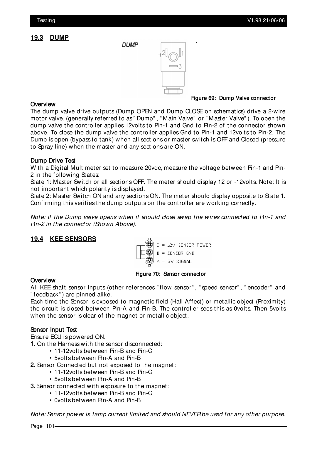
19.3 DUMP | . |
|
Figure 69: Dump Valve connector
Overview
The dump valve drive outputs (Dump OPEN and Dump CLOSE on schematics) drive a
Dump Drive Test
With a Digital Multimeter set to measure 20vdc, measure the voltage between
2 in the following States:
State 1: Master Switch or all sections OFF. The meter should display 12 or
State 2: Master Switch ON and any sections ON. The meter should display opposite to State 1. Confirming this verifies the dump outputs on the controller are working correctly.
Note: If the Dump valve opens when it should close swap the wires connected to
19.4KEE SENSORS
Figure 70: Sensor connector
Overview
All KEE shaft sensor inputs (other references "flow sensor", "speed sensor", "encoder" and "feedback") are pinned alike.
Each time the Sensor is exposed to magnetic field (Hall Affect) or metallic object (Proximity) the circuit is closed between
Sensor Input Test
Ensure ECU is powered ON.
1.On the Harness with the sensor disconnected:
•
•5volts between
2.Sensor Connected but not exposed to the magnet:
•
•5volts between
3.Sensor connected with exposure to the magnet:
•
•0volts between
Note: Sensor power is 1amp current limited and should NEVER be used for any other purpose.
Page 101