Installation of Spray ECU 30S KEE Sprayer Kits | V1.98 21/06/06 |
|
|
2.Glue the magnets to the wheel studs with the side marked with a cross (+) facing the Shaft/Speed Sensor. Use any silicone or epoxy type adhesive allowing adequate time to set. Ensure that the magnets are spaced equally around the wheel to ensure accurate speed update. To ensure adequate speed update place magnets onto ALL of the available wheel studs. A Wheel Calibration Factor of no greater than 0.6m (24 inches) is required. Please note that the Hose Clamp and Magnetic Block are not used in this case.
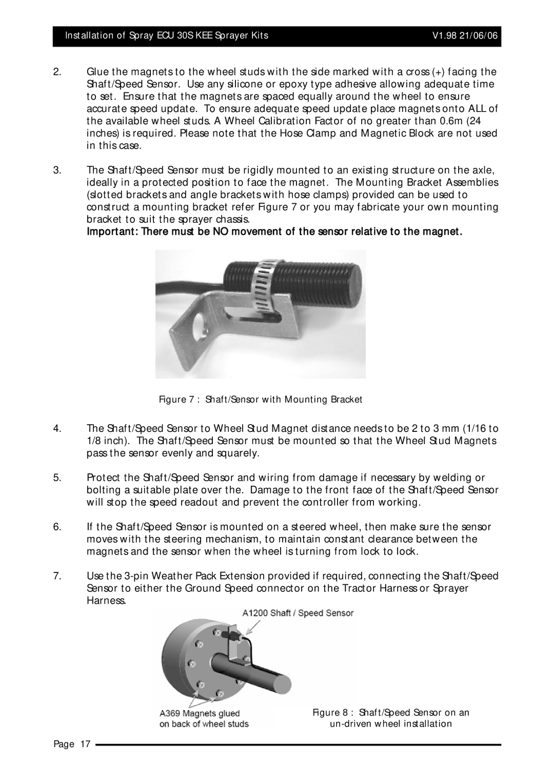
3.The Shaft/Speed Sensor must be rigidly mounted to an existing structure on the axle, ideally in a protected position to face the magnet. The Mounting Bracket Assemblies (slotted brackets and angle brackets with hose clamps) provided can be used to construct a mounting bracket refer Figure 7 or you may fabricate your own mounting bracket to suit the sprayer chassis.
Important: There must be NO movement of the sensor relative to the magnet.
Figure 7 : Shaft/Sensor with Mounting Bracket
4.The Shaft/Speed Sensor to Wheel Stud Magnet distance needs to be 2 to 3 mm (1/16 to 1/8 inch). The Shaft/Speed Sensor must be mounted so that the Wheel Stud Magnets pass the sensor evenly and squarely.
5.Protect the Shaft/Speed Sensor and wiring from damage if necessary by welding or bolting a suitable plate over the. Damage to the front face of the Shaft/Speed Sensor will stop the speed readout and prevent the controller from working.
6.If the Shaft/Speed Sensor is mounted on a steered wheel, then make sure the sensor moves with the steering mechanism, to maintain constant clearance between the magnets and the sensor when the wheel is turning from lock to lock.
7.Use the
Figure 8 : Shaft/Speed Sensor on an
un-driven wheel installation
Page 17
