Testing | V1.98 21/06/06 |
|
|
19.1REGULATOR
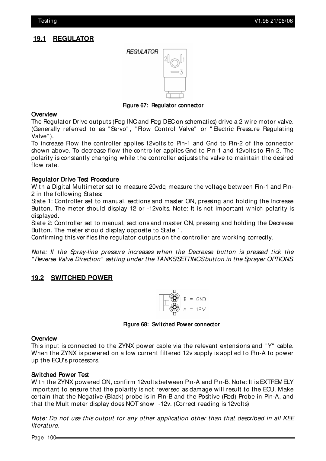
Figure 67: Regulator connector
Overview
The Regulator Drive outputs (Reg INC and Reg DEC on schematics) drive a
To increase Flow the controller applies 12volts to
Regulator Drive Test Procedure
With a Digital Multimeter set to measure 20vdc, measure the voltage between
2 in the following States:
State 1: Controller set to manual, sections and master ON, pressing and holding the Increase
Button. The meter should display 12 or
State 2: Controller set to manual, sections and master ON, pressing and holding the Decrease Button. The meter should display opposite to State 1.
Confirming this verifies the regulator outputs on the controller are working correctly.
Note: If the
19.2SWITCHED POWER
Figure 68: Switched Power connector
Overview
This input is connected to the ZYNX power cable via the relevant extensions and "Y" cable. When the ZYNX is powered on a low current filtered 12v supply is applied to
Switched Power Test
With the ZYNX powered ON, confirm 12volts between
Note: Do not use this output for any other application other than that described in all KEE literature.
Page 100