1 Hardware Overview | 1.1 Features |
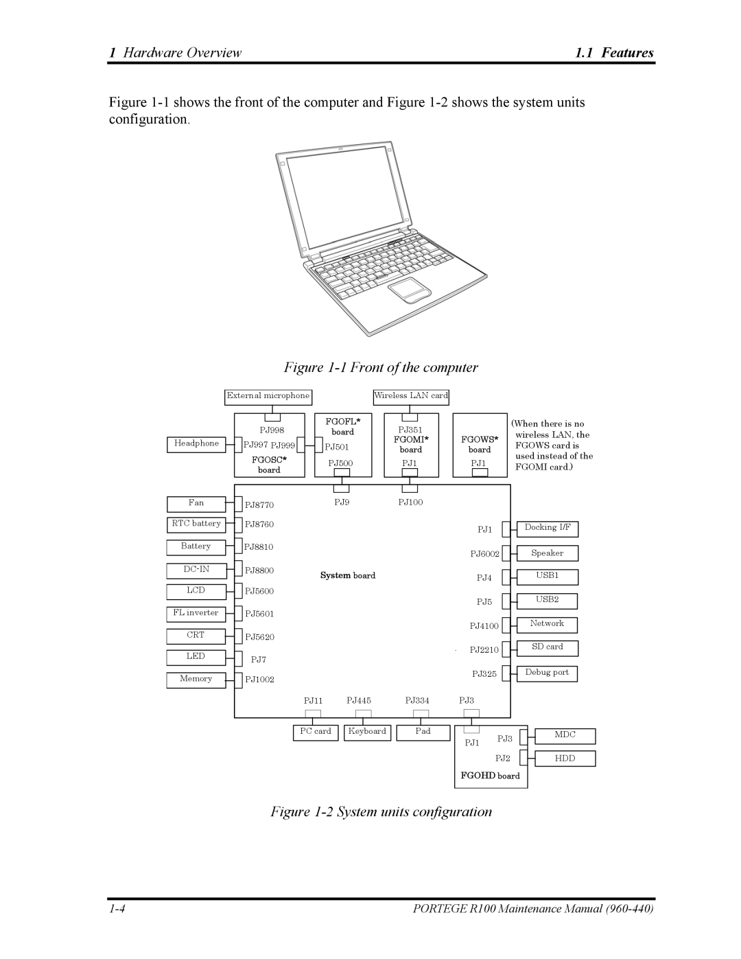
Figure 1-1 shows the front of the computer and Figure 1-2 shows the system units configuration.
Figure 1-1 Front of the computer
Headphone
External microphone
PJ998
PJ997 PJ999
FGOSC*
board
FGOFL*
board
PJ501
PJ500
Wireless LAN card
PJ351
FGOMI*
board
PJ1
FGOWS*
board
PJ1
(When there is no wireless LAN, the FGOWS card is used instead of the FGOMI card.)
Fan
RTC battery ![]()
![]()
Battery
LCD
FL inverter
CRT
LED
Memory
PJ8770 |
|
| PJ9 |
|
| PJ100 |
|
|
|
| |||
|
|
|
|
|
|
| |||||||
PJ8760 |
|
|
|
|
|
|
|
|
|
|
| PJ1 | |
|
|
|
|
|
|
|
|
|
|
|
| ||
PJ8810 |
|
|
|
|
|
|
|
|
|
|
| PJ6002 | |
|
|
|
|
|
|
|
|
|
|
|
| ||
PJ8800 | System board |
|
|
|
|
|
|
|
| ||||
|
|
|
|
|
| PJ4 | |||||||
|
|
|
|
|
|
| |||||||
PJ5600 |
|
|
|
|
|
|
|
|
|
|
|
|
|
|
|
|
|
|
|
|
|
|
|
|
|
| |
|
|
|
|
|
|
|
|
|
|
| PJ5 | ||
PJ5601 |
|
|
|
|
|
|
|
|
|
|
| ||
|
|
|
|
|
|
|
|
|
|
|
|
| |
PJ5620 |
|
|
|
|
|
|
|
|
|
|
| PJ4100 | |
|
|
|
|
|
|
|
|
|
|
|
|
| |
|
|
|
|
|
|
|
|
|
|
|
|
| |
PJ7 |
|
|
|
|
|
|
|
|
|
|
| PJ2210 | |
|
|
|
|
|
|
|
|
|
|
|
|
| |
PJ1002 |
|
|
|
|
|
|
|
|
|
|
| PJ325 | |
|
|
|
|
|
|
|
|
|
|
|
|
| |
|
|
|
|
|
|
|
|
|
|
|
|
| |
|
|
|
|
|
|
|
|
|
|
|
|
| |
| PJ11 |
|
| PJ445 |
|
| PJ334 |
| PJ3 |
| |||
|
|
|
|
|
|
|
|
|
|
|
|
|
|
Docking I/F
Speaker
USB1
USB2
Network
SD card
Debug port
PC card ![]()
![]() Keyboard
Keyboard
Pad
PJ1 PJ3
PJ2
FGOHD board
MDC
HDD
Figure 1-2 System units configuration
PORTEGE R100 Maintenance Manual |