Mechanical Locks and Monitoring
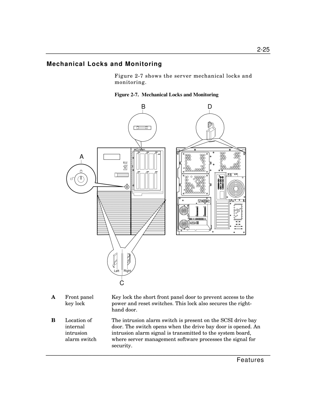
Figure 2-7 shows the server mechanical locks and monitoring.
Figure 2-7. Mechanical Locks and Monitoring
BD
A
POWER |
STATUS |
DISK |
|
|
|
|
|
|
|
|
|
|
|
|
|
|
|
|
|
|
|
|
|
|
| Left | Right | |||
|
|
|
|
|
| |
|
|
|
|
| ||
|
|
|
|
|
| |
|
|
| C | |||
A | Front panel | Key lock the short front panel door to prevent access to the | ||||
| key lock | power and reset switches. This lock also secures the right- | ||||
|
| hand door. | ||||
B | Location of | The intrusion alarm switch is present on the SCSI drive bay | ||||
| internal | door. The switch opens when the drive bay door is opened. An | ||||
| intrusion | intrusion alarm signal is transmitted to the system board, | ||||
| alarm switch | where server management software processes the signal for | ||||
|
| security. | ||||