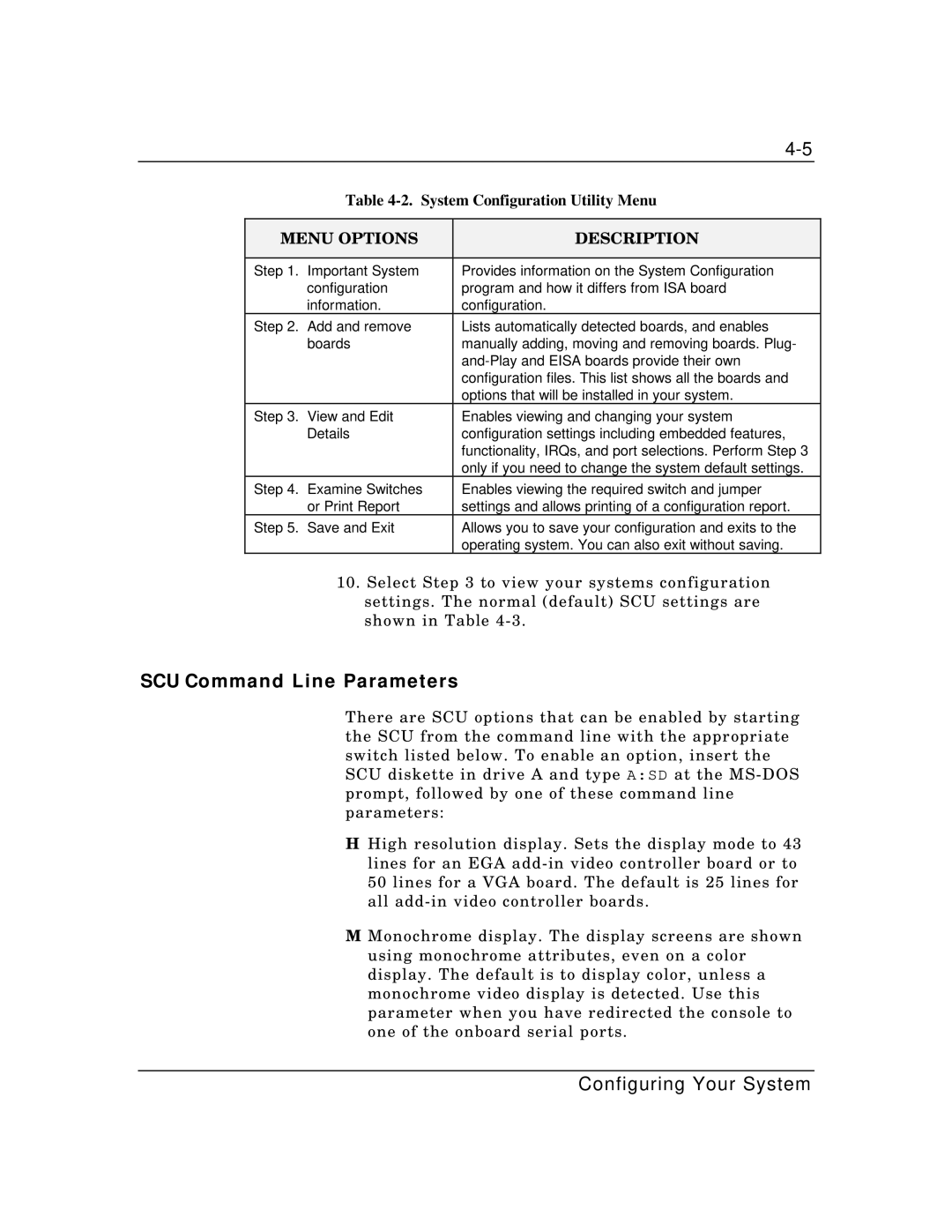
Table 4-2. System Configuration Utility Menu
MENU OPTIONS | DESCRIPTION | |
|
|
|
Step 1. | Important System | Provides information on the System Configuration |
| configuration | program and how it differs from ISA board |
| information. | configuration. |
Step 2. | Add and remove | Lists automatically detected boards, and enables |
| boards | manually adding, moving and removing boards. Plug- |
|
| |
|
| configuration files. This list shows all the boards and |
|
| options that will be installed in your system. |
Step 3. | View and Edit | Enables viewing and changing your system |
| Details | configuration settings including embedded features, |
|
| functionality, IRQs, and port selections. Perform Step 3 |
|
| only if you need to change the system default settings. |
Step 4. | Examine Switches | Enables viewing the required switch and jumper |
| or Print Report | settings and allows printing of a configuration report. |
Step 5. | Save and Exit | Allows you to save your configuration and exits to the |
|
| operating system. You can also exit without saving. |
10.Select Step 3 to view your systems configuration settings. The normal (default) SCU settings are shown in Table
SCU Command Line Parameters
There are SCU options that can be enabled by starting the SCU from the command line with the appropriate switch listed below. To enable an option, insert the SCU diskette in drive A and type A:SD at the
H High resolution display. Sets the display mode to 43 lines for an EGA
M Monochrome display. The display screens are shown using monochrome attributes, even on a color display. The default is to display color, unless a monochrome video display is detected. Use this parameter when you have redirected the console to one of the onboard serial ports.
Configuring Your System