18 | 1 System tour |
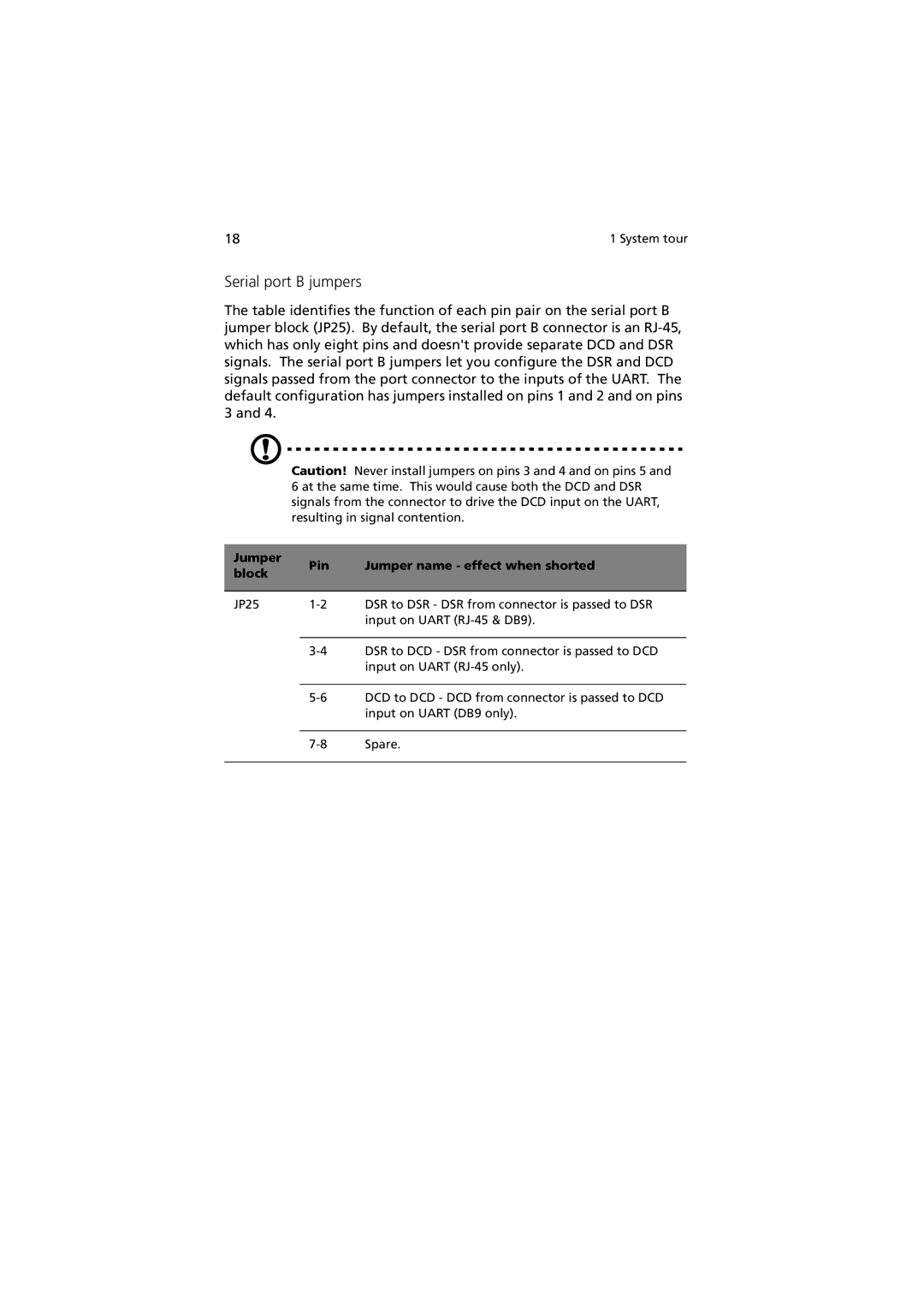
Serial port B jumpers
The table identifies the function of each pin pair on the serial port B jumper block (JP25). By default, the serial port B connector is an
Caution! Never install jumpers on pins 3 and 4 and on pins 5 and 6 at the same time. This would cause both the DCD and DSR signals from the connector to drive the DCD input on the UART, resulting in signal contention.
Jumper | Pin | Jumper name - effect when shorted | |
block | |||
|
| ||
|
|
| |
JP25 | DSR to DSR - DSR from connector is passed to DSR | ||
|
| input on UART | |
|
|
| |
| DSR to DCD - DSR from connector is passed to DCD | ||
|
| input on UART | |
|
|
| |
| DCD to DCD - DCD from connector is passed to DCD | ||
|
| input on UART (DB9 only). | |
|
|
| |
| Spare. | ||
|
|
|