Manuals
/
Acer
/
Computer Equipment
/
Server
Acer
G901
manual
Push the handle closed until it clicks into position, Installing a drive carrier
Models:
G901
1
96
244
244
Download
244 pages
26.92 Kb
93
94
95
96
97
98
99
100
Troubleshooting
Install
Error codes
Password
Adapter Fault Tolerance
Hot-plug indicator board
Hardware configuration
Reset to Bios setup defaults
Access covers
Bios setup 109
Page 96
Image 96
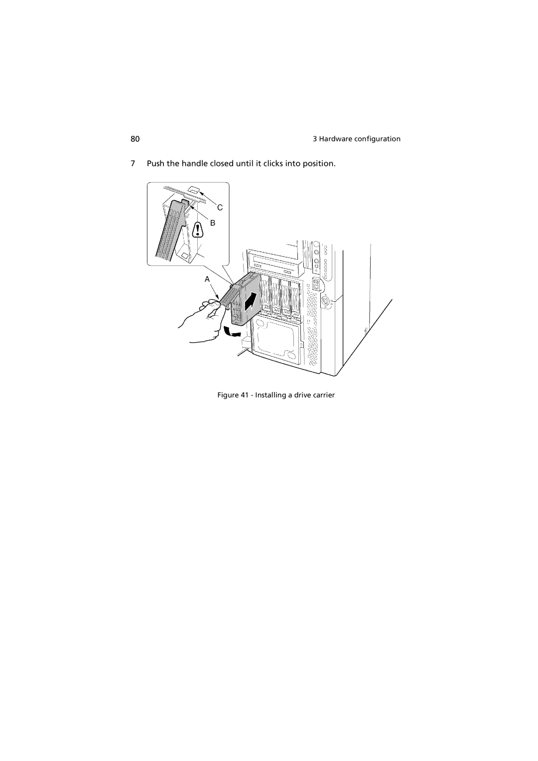
80
3 Hardware configuration
7 Push the handle closed until it clicks into position.
Figure 41 - Installing a drive carrier
Page 95
Page 97
Page 96
Image 96
Page 95
Page 97
Contents
Acer Altos G900
User’s guide
Page
FCC notice
Iii
Laser compliance statement
Use conditions
Important safety information
Checking the power cords
Intended application uses
Precautionary reminders
Multiple power cords Earth grounded socket-outlets
Equipment rack precautions
Vii
Important safety instructions
Viii
Page
Page
Contents
Hardware configuration
Bios setup 109
Appendix a System rack installation 143
Appendix B System management 159
Appendix C Equipment log and configuration worksheets
Appendix D Troubleshooting 199
Appendix E Codes and error messages 211
Index 227
Xvi
System tour
Page
Features overview
Altos G900 physical specifications
Specification Rack-mount orientation Tower orientation
Access covers
External and internal structure
Label Description
Main chassis components
Main chassis components
Electronics bay components
Electronics bay components
Front control panel
Label Description Operation
LAN2 LED
Figure below describes the features of the rear panel
Rear panel
Video connector
Peripheral device bay
Peripheral device bay
Server board set features
Mainboard layout
Label Description
Mainboard jumpers
Boot block jumpers
Jumper Pins Jumper name effect when shorted Block
Jumper Pin Jumper name effect when shorted Block
Serial port B jumpers
System cables
Cables to the subchassis
Front cables in the cable clamp
Rear cables in the cable clamp
System features
Processors
Memory
Scsi controller
Onboard video
Network interface controllers
Hot-swap hard drive bays
Power supply
System fan
Acpi
System setup
Page
Getting started
Checking for damage to the packaging
Selecting a site
Checking the package contents
Page
Setting up your system
Setup reminders
Pre-setup safety steps
Hardware setup
System setup
Hot keys for Post
To do this Press these keys
Software setup
Installing the service partition recommended
Installing the operating system
Network teaming features
NIC connector and status LEDs
Adapter Fault Tolerance
Adaptive Load Balancing
Hardware configuration
Page
Installation precautions
ESD precautions
Preinstallation instructions
Post-installation instructions
Tools and supplies needed
System access panels
Before removing the access panels
Rear access panel
To remove the rear access panel
Front access panel
To install the rear access panel
Lift the panel away from the chassis
To remove the front access panel
To install the front access panel
Front subchassis and rear electronics bay
Opening the front subchassis and rear electronics bay
To open the front subchassis and rear electronics bay
Removing the front subchassis and rear electronics bay
To remove the front subchassis
Installing the front subchassis and rear electronics bay
To install the front subchassis
To install the electronics bay
To remove the electronics bay
Closing the front subchassis and rear electronics bay
To close the front subchassis and rear electronics bay
Accessing the system boards
Access cover to the system boards
To remove the access cover to the system boards
To install the access cover to the system boards
Memory board
To remove the memory board
To install the memory board
Installing the memory board
To install the processor board
Processor board
To remove the processor board
Mainboard
To remove the mainboard
Removing the front retention mechanism
Mainboard mounting
To install the mainboard
Page
To install DIMMs
Memory
Dimm sequence
Installing a Dimm
To remove DIMMs
Removing a Dimm
Processors
Processor sequence
To install processors
Raise the locking bar on the socket
Installing the heatsink
To remove processors
Removing the heatsink clips
PCI add-in boards
PCI add-in board locations
Checking the status indicators for a hot-plug add-in board
Power LED state Status
Operating system support for hot-plug add-in boards
Installing and removing a hot-plug PCI add-in board
To install a hot-plug PCI add-in board
Installing a hot-plug PCI add-in board
To remove a hot-plug PCI add-in board
Removing a hot-plug PCI add-in board
Installing and removing a non-hot-plug PCI add-in board
To install a PCI add-in board in a non-hot-plug slot
To remove a PCI add-in board from a non-hot-plug slot
Checking a hot-swap Scsi drive status indicator
Hot-swap Scsi drives
Installing and removing a hot-swap drive in a carrier
To install a hot-swap drive in a carrier
LED state Status
Installing a Scsi hard disk drive in a carrier
Removing and installing hot-swap disk drives
To install a hot-swap disk drive
To remove a hot-swap drive from a carrier
Removing a drive carrier
Installing a drive carrier
Push the handle closed until it clicks into position
DC power supplies
Checking the power supply LED status indicators
Removing and installing a power supply module
To remove a power supply module
Power Predictive Fail Status Green Amber
Removing a power supply module
To install a power supply module
Checking a fan status indicator
Cooling system fans
Altos G900 server accommodates six hot-swap fan modules
Removing and installing a fan module
To install a fan module
To remove a fan module
Backup battery
Replacing the battery
Removing the battery
Installing the front panel board
Front panel board
Label Description
Diskette drive
Replacing the diskette drive
Inserting a diskette drive into the bracket
Page
Inch peripheral drives
Preliminary considerations
Drive cables
Removing and installing a 5.25-inch peripheral drive
EMC compliance of 5.25-inch removable media device bays
To install a 5.25-inch peripheral drive
To remove a a 5.25-inch peripheral drive
Page
Removing and installing a hot-swap drive bay
Hot-swap drive bays
To remove a hot-swap drive bay
To install a hot-swap drive bay
100 Hardware configuration
Power distribution board
Replacing the power distribution board
102 Hardware configuration
Fan distribution board
Replacing the fan distribution board
104 Hardware configuration
Removing and installing the foam fan baffle
Foam fan baffle
To remove the foam fan baffle
To install the foam fan baffle
Hot-plug indicator board
Replacing the hot-plug indicator board
108 Hardware configuration
Bios setup
Page
Bios setup
Recording Bios settings
Clearing Cmos memory
Using Bios setup
To clear the Cmos memory using the front panel buttons
Reset to Bios setup defaults
113
Disabled
Main
Parameter Description Option
44/1,25 MB, 3.5-inch
115
Primary IDE Master/Slave
117
Auto
Standard
Processor Settings
Parameter Description
Advanced
PCI
Boot
120
Off
Memory Configuration
Normal
PCI Configuration
Hot-plug PCI Control
123
Empty Bus Default Speed
Enabled
Embedded Scsi
125
Embedded NIC 1 10/100
Embedded NIC 2 Gbit
127
Embedded Voice Controller
Device Configuration
PCI Slot 1
This submenu lets you initialize device expansion ROM
130
Advanced Chipset Control
Present
Security
133
To set a security password
To change the Supervisor/User password
To remove the User/Supervisor password
135
Server
Disable BSP
137
Last State
System Management
Console Redirection
9600
VT100+
Boot
Exit
142
Installation
Page
System rack installation
Rack-mount kit contents
Tools and supplies needed
Rack-mount kit components
Precautions
Rack conversion procedures
Installation overview
Removing the bottom panel
Removing the left panel
Removing the bottom panel
Removing the original tower bezel
Removing the left panel
Removing the feet
Removing the original tower bezel
Installing the rack bezel
Removing the feet
Installing the bushings on the chassis
Installing the rack bezel
Installing the handles and rails
Installing the bushings
Install the outer rails to the rack
Sliding out the inner rails
156 Attach the inner rails to the server
Attach the rack handles to the server
157 Slide the server into the rack
Mounting the server to the rack
158 Appendix a System rack installation
Management
Page
Software and utilities
SCSISelect
Integrated hardware system management
Baseboard management controller
Field replaceable units and sensor data records
System event log
Platform event management
Emergency management port
System Setup Utility
Creating SSU diskettes
Follow the instructions displayed
Running the SSU
To start the SSU
Working with the GUI
Customizing the SSU interface
Setting boot device priority
Setting passwords and security options
Setting the admin password
Setting the user password
Setting security options
Viewing the system event log
Viewing FRU information
Viewing Sensor Data Records
Updating system firmware and Bios
Saving and restoring the system configuration
To verify the firmware
To save the system configuration
To restore the system configuration
Alerting for platform events
To set up paging alerts
Maximum length for the string is five
Characters longer strings are truncated
Page
To set up LAN alerts
Setting up remote LAN access
Managing the server remotely
Are ignored
Setting up remote modem or serial access
Exiting the SSU
Exiting the SSU closes all SSU windows
When to run the FRU/SDR load utility
FRU/SDR load utility
Running the FRU/SDR load utility
Command line format
Basic command line format is
Displaying a given area
Using a specified CFG file
Using a specified FRU file
Updating nonvolatile storage areas
185
SCSISelect
Running SCSISelect
Software updates
Creating bootable diskettes
Software update packages
To install a software update package
At the DOS prompt, for an unformatted diskette, type
Or, for an already formatted diskette, type
Individual updates
Bios updates
Firmware updates
Changing the Bios language
FRU/SDR updates
192 Appendix B System management
Configuration worksheets
Page
Manufacturer Name Serial Date Model Number Installed
Equipment log
Calculating power consumption
Calculating DC power usage
Power Usage Worksheet Device Current maximum voltage level
197
Calculating the total combined power used by the system
Fans Total Current
Troubleshooting
Page
Troubleshooting
Resetting the system
Initial system startup
To do this Press
Application software checklist
Running new application software
After the system has been running correctly
Monitoring Post
Verifying proper operation of key system lights
Confirming loading of an operating system
Frequently asked questions FAQs
206 Appendix D Troubleshooting
Page
208 Appendix D Troubleshooting
Page
210 Appendix D Troubleshooting
Messages
Page
Standard Bios post codes
Beeps Reason
214
215
216
217
218
Recovery Bios Post codes
220
BMC beep codes
Table below lists the beep codes generated by the BMC
Post error messages and codes
Code Error Message Failure Description
Setup
223
224
225
226
Index
227
228
Top
Page
Image
Contents