56 | 3 Hardware configuration |
For a diagram showing labeled connectors, refer to “Mainboard layout” on page 13.
6Remove all cables from the cable retention clip on the front of the electronics bay.
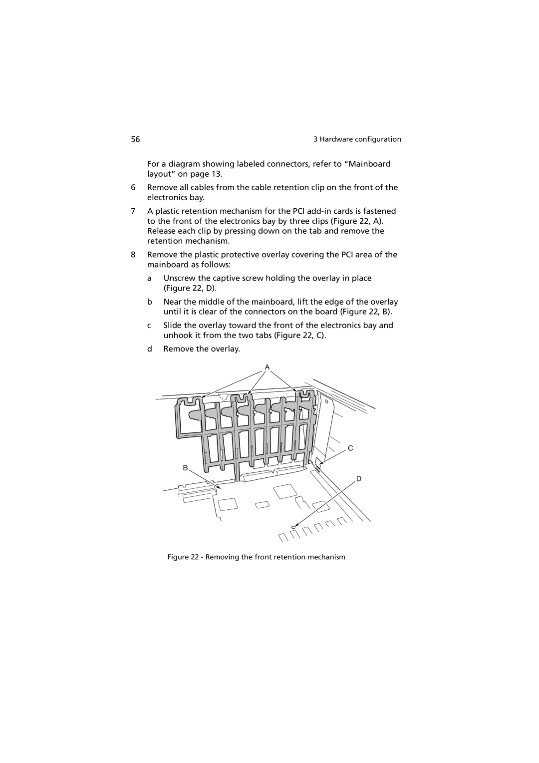
7A plastic retention mechanism for the PCI
8Remove the plastic protective overlay covering the PCI area of the mainboard as follows:
a Unscrew the captive screw holding the overlay in place (Figure 22, D).
b Near the middle of the mainboard, lift the edge of the overlay until it is clear of the connectors on the board (Figure 22, B).
c Slide the overlay toward the front of the electronics bay and unhook it from the two tabs (Figure 22, C).
d Remove the overlay.