57
Label | Description | Label | Description |
|
|
|
|
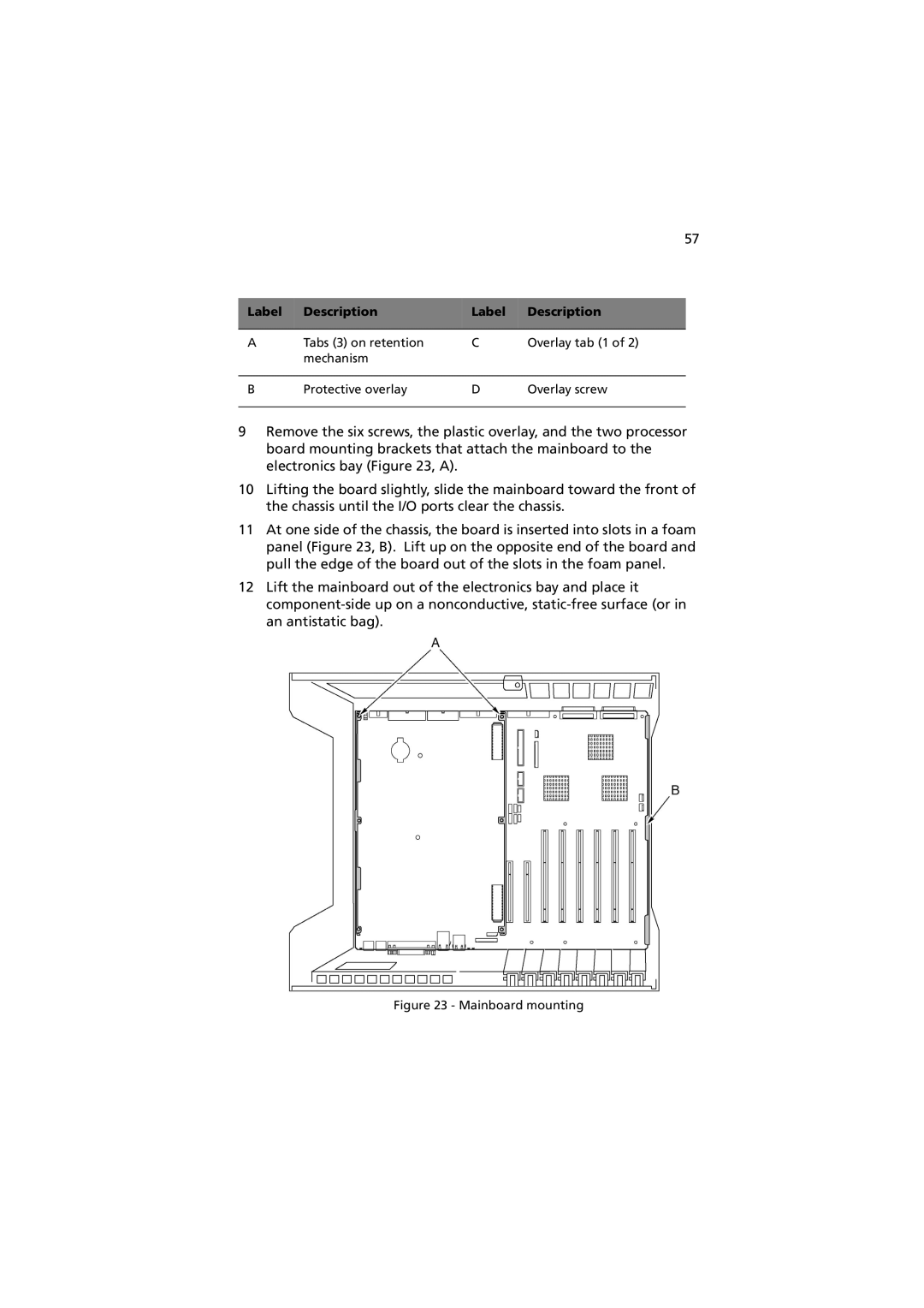
A | Tabs (3) on retention | C | Overlay tab (1 of 2) |
| mechanism |
|
|
|
|
|
|
B | Protective overlay | D | Overlay screw |
|
|
|
|
9Remove the six screws, the plastic overlay, and the two processor board mounting brackets that attach the mainboard to the electronics bay (Figure 23, A).
10Lifting the board slightly, slide the mainboard toward the front of the chassis until the I/O ports clear the chassis.
11At one side of the chassis, the board is inserted into slots in a foam panel (Figure 23, B). Lift up on the opposite end of the board and pull the edge of the board out of the slots in the foam panel.
12Lift the mainboard out of the electronics bay and place it