82 | 3 Hardware configuration |
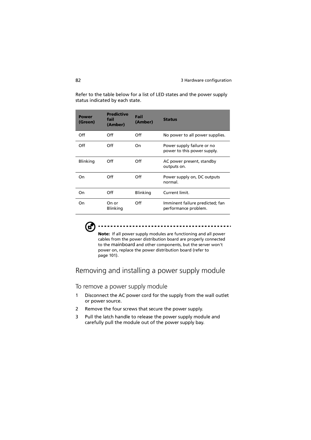
Refer to the table below for a list of LED states and the power supply status indicated by each state.
Power | Predictive | Fail |
| |
fail | Status | |||
(Green) | (Amber) | |||
(Amber) |
| |||
|
|
| ||
|
|
|
| |
Off | Off | Off | No power to all power supplies. | |
|
|
|
| |
Off | Off | On | Power supply failure or no | |
|
|
| power to this power supply. | |
|
|
|
| |
Blinking | Off | Off | AC power present, standby | |
|
|
| outputs on. | |
|
|
|
| |
On | Off | Off | Power supply on, DC outputs | |
|
|
| normal. | |
|
|
|
| |
On | Off | Blinking | Current limit. | |
|
|
|
| |
On | On or | Off | Imminent failure predicted; fan | |
| Blinking |
| performance problem. | |
|
|
|
|
Note: If all power supply modules are functioning and all power cables from the power distribution board are properly connected to the mainboard and other components, but the server won't power on, replace the power distribution board (refer to
page 101).
Removing and installing a power supply module
To remove a power supply module
1Disconnect the AC power cord for the supply from the wall outlet or power source.
2Remove the four screws that secure the power supply.
3Pull the latch handle to release the power supply module and carefully pull the module out of the power supply bay.
