2 - Introduction to Programming

System Considerations

The remainder of this chapter addresses some system issues concerning programming. These are ac source addressing and the use of the following types of GPIB system interfaces:

υHP Vectra PC controller with Agilent 82335A GPIB Interface Command Library

υIBM PC controller with National Instruments GPIB-PCII Interface/Handler

υAgilent controller with Agilent BASIC Language System

Assigning the GPIB Address in Programs

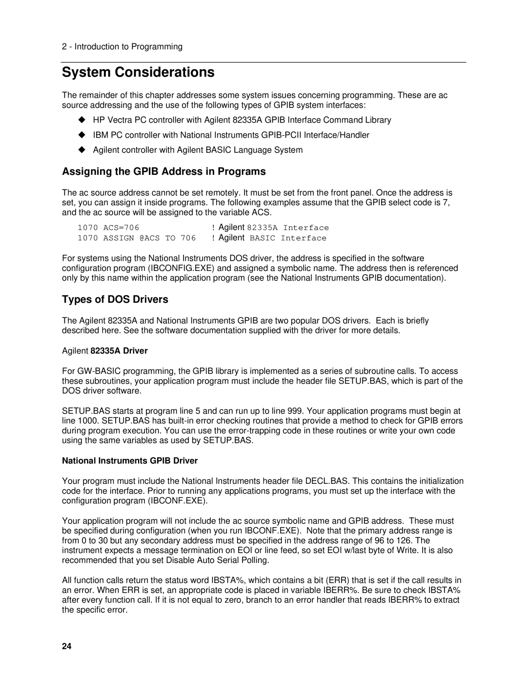
The ac source address cannot be set remotely. It must be set from the front panel. Once the address is set, you can assign it inside programs. The following examples assume that the GPIB select code is 7, and the ac source will be assigned to the variable ACS.

1070

ACS=706

! Agilent 82335A Interface

1070

ASSIGN @ACS TO 706

! Agilent BASIC Interface

For systems using the National Instruments DOS driver, the address is specified in the software configuration program (IBCONFIG.EXE) and assigned a symbolic name. The address then is referenced only by this name within the application program (see the National Instruments GPIB documentation).

Types of DOS Drivers

The Agilent 82335A and National Instruments GPIB are two popular DOS drivers. Each is briefly described here. See the software documentation supplied with the driver for more details.

Agilent 82335A Driver

For GW-BASIC programming, the GPIB library is implemented as a series of subroutine calls. To access these subroutines, your application program must include the header file SETUP.BAS, which is part of the DOS driver software.

SETUP.BAS starts at program line 5 and can run up to line 999. Your application programs must begin at line 1000. SETUP.BAS has built-in error checking routines that provide a method to check for GPIB errors during program execution. You can use the error-trapping code in these routines or write your own code using the same variables as used by SETUP.BAS.

National Instruments GPIB Driver

Your program must include the National Instruments header file DECL.BAS. This contains the initialization code for the interface. Prior to running any applications programs, you must set up the interface with the configuration program (IBCONF.EXE).

Your application program will not include the ac source symbolic name and GPIB address. These must be specified during configuration (when you run IBCONF.EXE). Note that the primary address range is from 0 to 30 but any secondary address must be specified in the address range of 96 to 126. The instrument expects a message termination on EOI or line feed, so set EOI w/last byte of Write. It is also recommended that you set Disable Auto Serial Polling.

All function calls return the status word IBSTA%, which contains a bit (ERR) that is set if the call results in an error. When ERR is set, an appropriate code is placed in variable IBERR%. Be sure to check IBSTA% after every function call. If it is not equal to zero, branch to an error handler that reads IBERR% to extract the specific error.

24

Page 24
Image 24
Agilent Technologies 6834B, 6814B manual System Considerations, Assigning the Gpib Address in Programs, Types of DOS Drivers

6812B, 6811B, 6813B, 6834B, 6843A specifications

Agilent Technologies, a leader in electronic test and measurement equipment, offers a range of powerful signal sources including the 6843A, 6834B, 6814B, 6813B, and 6811B models. These instruments are designed to support various applications in research, development, and manufacturing, providing precise signal generation capabilities.

The Agilent 6843A is a versatile signal generator known for its exceptional frequency range and modulation capabilities. It supports an extensive bandwidth, making it ideal for applications that require high-frequency signal generation. With its superior phase noise performance, the 6843A is an excellent choice for radar, wireless communications, and electronic warfare applications. The instrument features an intuitive user interface, allowing engineers to set parameters quickly and efficiently.

Next, the Agilent 6834B offers exceptional performance characteristics, including high output power and low distortion. This signal generator is particularly noted for its ability to produce complex modulation formats, making it suitable for testing advanced wireless communication systems. With a reliable and stable output, the 6834B ensures accurate and repeatable measurements, which is vital for thorough testing processes.

The 6814B model stands out for its dual-channel capabilities, allowing users to generate simultaneous signals for testing multiple components or systems. This feature significantly enhances testing efficiency and flexibility for engineers. With built-in arbitrary waveform functionality, users can create custom waveforms, making the 6814B suitable for a wide range of applications including device characterization and signal processing research.

For those seeking a more compact solution, the Agilent 6813B provides essential signal generation features without compromising on performance. It is designed for a variety of applications across telecommunications and consumer electronics, featuring a straightforward interface and robust performance metrics.

Lastly, the 6811B is an entry-level yet capable model that supports a broad spectrum of testing needs. Perfect for educational and laboratory environments, it provides essential functionalities required for effective signal generation and analysis.

Overall, Agilent Technologies' 6843A, 6834B, 6814B, 6813B, and 6811B signal generators offer an array of features and technologies that cater to various application needs. Their precision, reliability, and user-oriented designs position them as invaluable assets in any testing environment, ensuring engineers can carry out their work with confidence and accuracy.