HARDWARE INSTALLATION
The intelligent LED controller outputs a
The SATA RAID controller provides four kinds of LED status connec- tors.
A:Global indicator connector, which lights when any drive is active.
B:Individual LED indicator connector, for each drive channel.
C:I2C connector, for SATA proprietary backplane enclosure.
D:SGPIO connector for SAS Backplane enclosure
The following diagrams and description describes each type of con- nector.
Note:
A cable for the global indicator comes with your computer system. Cables for the individual drive LEDs may come with a drive cage, or you may need to purchase them.
A: Global Indicator Connector
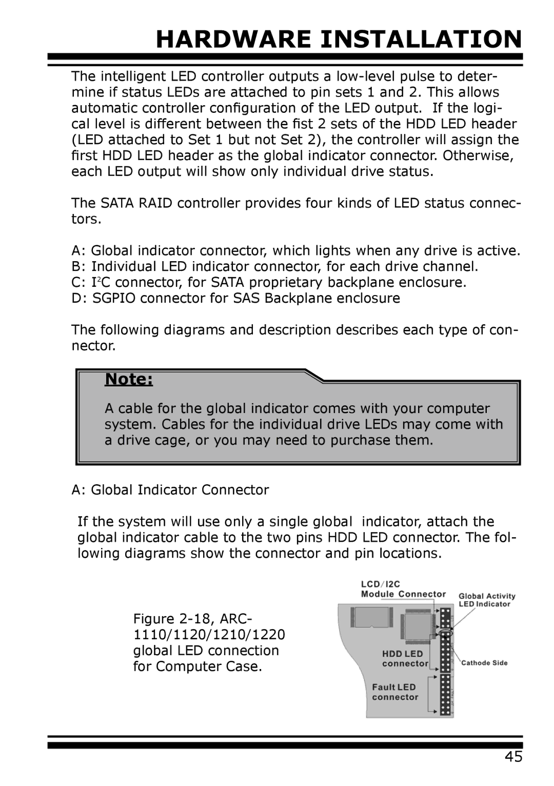
If the system will use only a single global indicator, attach the global indicator cable to the two pins HDD LED connector. The fol- lowing diagrams show the connector and pin locations.
Figure 2-18, ARC- 1110/1120/1210/1220 global LED connection for Computer Case.
45