HARDWARE INSTALLATION
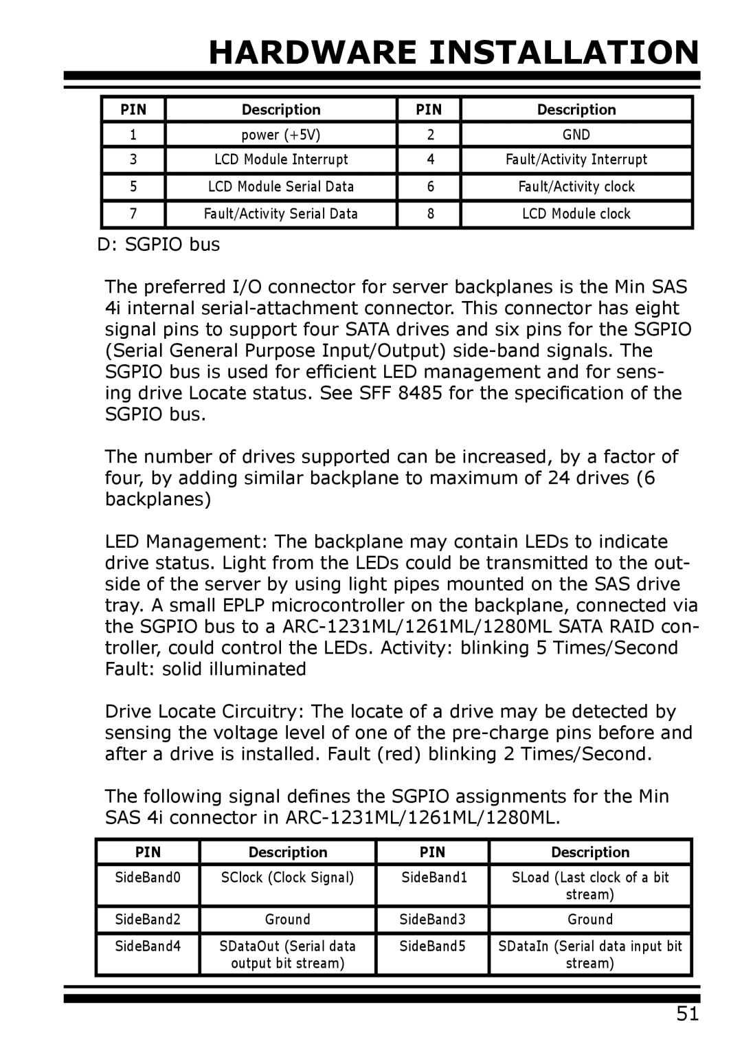
PIN | Description | PIN | Description |
|
|
|
|
1 | power (+5V) | 2 | GND |
|
|
|
|
3 | LCD Module Interrupt | 4 | Fault/Activity Interrupt |
|
|
|
|
5 | LCD Module Serial Data | 6 | Fault/Activity clock |
|
|
|
|
7 | Fault/Activity Serial Data | 8 | LCD Module clock |
|
|
|
|
D: SGPIO bus
The preferred I/O connector for server backplanes is the Min SAS 4i internal
The number of drives supported can be increased, by a factor of four, by adding similar backplane to maximum of 24 drives (6 backplanes)
LED Management: The backplane may contain LEDs to indicate drive status. Light from the LEDs could be transmitted to the out- side of the server by using light pipes mounted on the SAS drive tray. A small EPLP microcontroller on the backplane, connected via the SGPIO bus to a
Drive Locate Circuitry: The locate of a drive may be detected by sensing the voltage level of one of the
The following signal defines the SGPIO assignments for the Min SAS 4i connector in
| PIN | Description | PIN | Description |
|
| SideBand0 | SClock (Clock Signal) | SideBand1 | SLoad (Last clock of a bit |
|
|
|
|
| stream) |
|
|
|
|
|
|
|
| SideBand2 | Ground | SideBand3 | Ground |
|
|
|
|
|
|
|
| SideBand4 | SDataOut (Serial data | SideBand5 | SDataIn (Serial data input bit |
|
|
| output bit stream) |
| stream) |
|
|
|
|
|
|
|
|
|
|
|
|
|
51