HARDWARE INSTALLATION
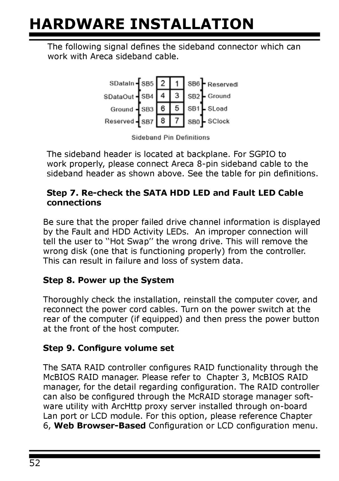
The following signal defines the sideband connector which can work with Areca sideband cable.
The sideband header is located at backplane. For SGPIO to work properly, please connect Areca
Step 7. Re-check the SATA HDD LED and Fault LED Cable connections
Be sure that the proper failed drive channel information is displayed by the Fault and HDD Activity LEDs. An improper connection will tell the user to ‘‘Hot Swap’’ the wrong drive. This will remove the wrong disk (one that is functioning properly) from the controller. This can result in failure and loss of system data.
Step 8. Power up the System
Thoroughly check the installation, reinstall the computer cover, and reconnect the power cord cables. Turn on the power switch at the rear of the computer (if equipped) and then press the power button at the front of the host computer.
Step 9. Configure volume set
The SATA RAID controller configures RAID functionality through the McBIOS RAID manager. Please refer to Chapter 3, McBIOS RAID manager, for the detail regarding configuration. The RAID controller can also be configured through the McRAID storage manager soft- ware utility with ArcHttp proxy server installed through
52