HARDWARE INSTALLATION
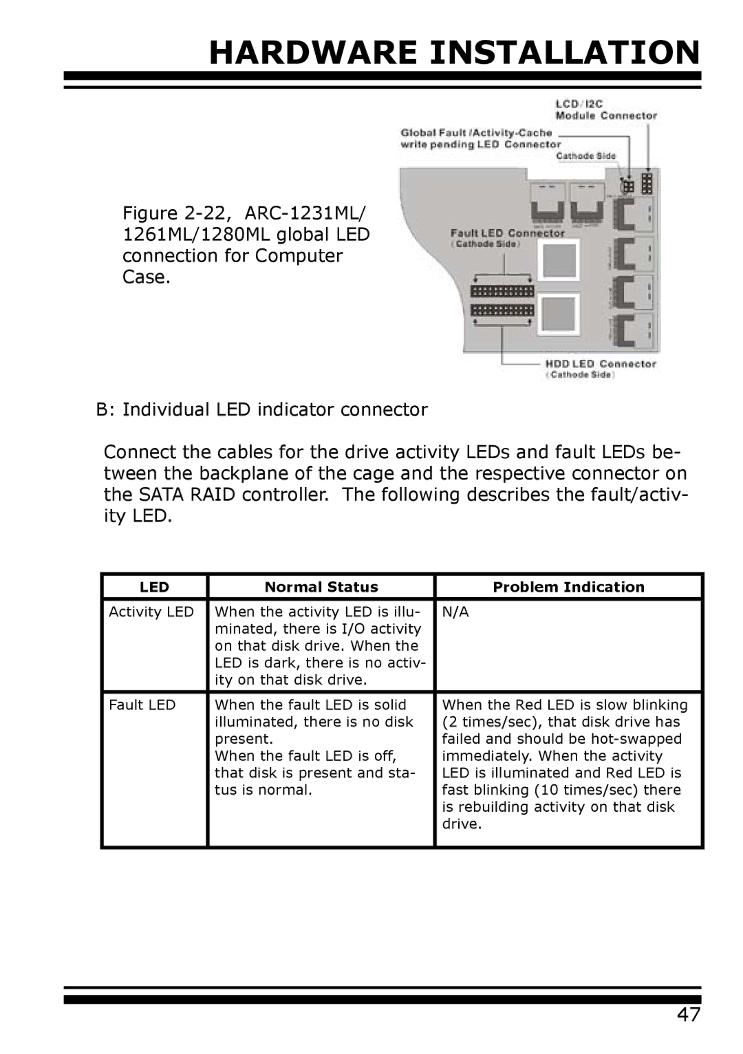
Figure 2-22, ARC-1231ML/ 1261ML/1280ML global LED connection for Computer Case.
B: Individual LED indicator connector
Connect the cables for the drive activity LEDs and fault LEDs be- tween the backplane of the cage and the respective connector on the SATA RAID controller. The following describes the fault/activ- ity LED.
LED | Normal Status | Problem Indication |
|
|
|
Activity LED | When the activity LED is illu- | N/A |
| minated, there is I/O activity |
|
| on that disk drive. When the |
|
| LED is dark, there is no activ- |
|
| ity on that disk drive. |
|
|
|
|
Fault LED | When the fault LED is solid | When the Red LED is slow blinking |
| illuminated, there is no disk | (2 times/sec), that disk drive has |
| present. | failed and should be |
| When the fault LED is off, | immediately. When the activity |
| that disk is present and sta- | LED is illuminated and Red LED is |
| tus is normal. | fast blinking (10 times/sec) there |
|
| is rebuilding activity on that disk |
|
| drive. |
|
|
|
47