581A155,180
FEATURES/BENEFITS
Sizes
579F180-216
Table of Contents
FEATURES/BENEFITS
FEATURES/BENEFITS
580F E V 060 120 N KB
Model Number Nomenclature
580F036-150 Standard and Medium Efficiency 3 to 121/2 Tons
581B036-150 High Efficiency 3 to 121/2 Tons
580F E V 180 275 - C B
Model Number Nomenclature 579F180-300
580F180-300
579F E V 180 230 - C B
A 2 5 0 - a
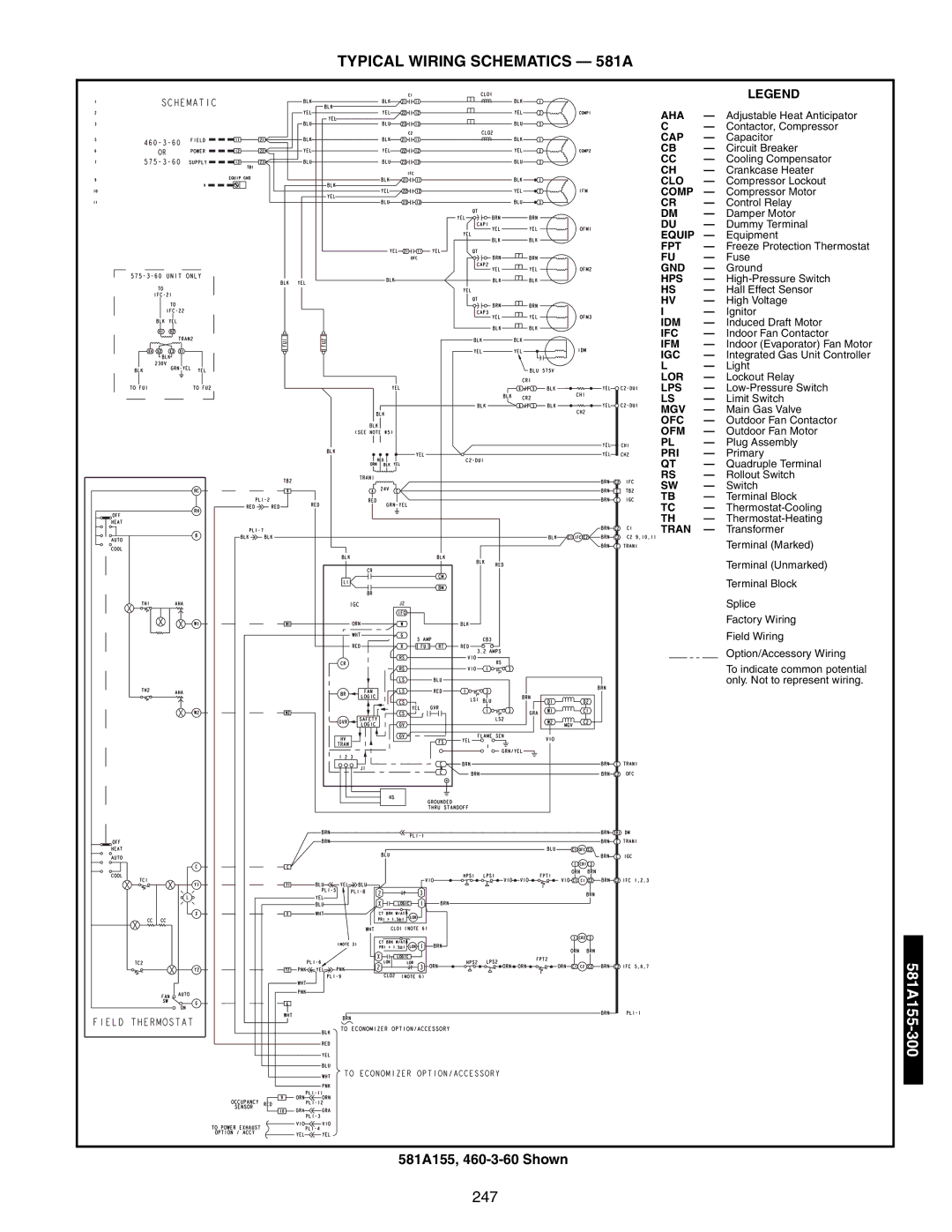
Model Number Nomenclature 581A155, 180, 181 13 to 15 Tons
581A210-300 18 to 25 Tons
581A E 180 230 - C B
ARI* Capacity Ratings 580F036-151
Unit
ARI* Capacity Ratings
Rise F Airflow CFM
Capacity Airflow CFM
Unit Nominal Cooling Total SEER† Sound Rating Iplv
Unit Input Capacity Output Capacity Temperature
ARI* Capacity Ratings 581B036-150
Heating Capacities and Efficiencies 581B036-150
Unit Input Capacity Output Capacity Temperatur
Heating Capacities and Efficiencies 581B036-150cont
Heating
AIR Quantity Limits
LOW Outdoor Temperature Operating Limits F
ARI* Capacity Ratings 579F180-300
Heating Capacities and Efficiencies 579F180-300
Heating Capacities and Efficiencies 580F180-300
ARI* Capacity Ratings 580F180-300
AIR Quantity Limits Cooling
ARI* Capacity Ratings 581A155,180
LOW Outdoor AIR Temperature Cooling Operation Limits
Heating Capacities and Efficiencies 581A155-180
Heating Capacities and Efficiencies 581A210-300
ARI* Capacity Ratings 581A210-300
Option ACCESSORY†
Options and Accessories 581B036-150 and 580F036-151
579F180-300, 580F180-300, and 581A155-181
Options and Accessories
581A210-300
Options and Accessories
151
Physical Data 580F036-073
Unit Size 580F
Furnace Section
Physical Data 580F090,120,150 Units
LOSS-OF-CHARGE LOW-PRESSURE
Physical Data 580F091,103,121,151 Units
580F036-151
Ashrae 90.1 Compliant Units
Ashrae 90.1 Compliant Units
Base Unit Dimensions 580F036-072
Base Unit Dimensions 580F073
Base Unit Dimensions 580F090,120,150
Base Unit Dimensions 580F091,103,121,151
Roof Curb
Accessory Dimensions 580F
Unit Size Accessory CRRFCURB001A01
ALT Accessory Drain GAS Power Control PKG. Accy Hole
Roof Curb Details
Accessory Dimensions 580F
II Select Unit Based on Required Cooling Capacity
Selection Procedure with 580F060 example
Determine NET Cooling Capacity
Entering AIR DRY-BULB Temp F
Performance Data
Cooling Capacities
SHC
Cooling Capacities
Performance Data
Factor
Bypass Entering AIR DRY-BULB Temp F
580F151 121/ Tons Temp F
FAN Performance Vertical Discharge Units
580F048 4 Tons HIGH-STATIC Motor Belt Drive
FAN Performance Vertical Discharge Units
580F048 4 Tons Standard Motor Direct Drive
580F048 4 Tons Alternate Motor Belt Drive
580F060 5 Tons Standard Motor Direct Drive
580F060 5 Tons SINGLE-PHASE, Alternate Motor Belt Drive
580F060 5 Tons HIGH-STATIC Motor Belt Drive
580F060 5 Tons THREE-PHASE, Alternate Motor Belt Drive
580F072,073 6 Tons HIGH-STATIC Motor Belt Drive
580F072,073 6 Tons Standard Motor Belt Drive
584
580F090,091 71/2 Tons Standard Motor Belt Drive
505
531
580F090,091 71/2 Tons Alternate Motor Belt Drive
580F090,091 71/2 Tons HIGH-STATIC Motor Belt Drive
580F103 81/2 Tons Standard Motor Belt DRIVE*
580F103 81/2 Tons Standard Motor Belt Drive
580F103 81/2 Tons HIGH-STATIC Motor Belt DRIVE*
580F103 81/2 Tons HIGH-STATIC Motor Belt Drive
958
962
978
942
580F120 10 Tons Alternate Motor Belt Drive
786 836 847 1016 905 1204 958
726 656 793 822 853 997 910
746 713 811 883 870 1062 926
766 773 829 947 887 1131 942
580F121 10 Tons Standard Motor Belt Drive
949
580F121 10 Tons Alternate Motor Belt Drive
580F121 10 Tons Alternate Motor Belt DRIVE* Airflow
1103 798
961 775
828
1030 787
804
580F150,151 121/ Tons Standard Motor Belt Drive
789
848
580F150,151 121/ Tons Alternate Motor Belt Drive
FAN Performance Horizontal Discharge Units
1600 1189 1191 1700 1800 1900 2000 Bhp
FAN Performance Horizontal Discharge Units
Airflow Low Speed Medium Speed High Speed 208V 230, 460, 575
Bhp Brake Horsepower Input to Fan
Performance Data FAN Performance Horizontal Discharge Units
561
484
681
509
894
901
708
766
1488
1119
1293
1388
3100 637 1046
2189
1783
1912
2047
580F120,121 10 Tons Standard Motor Belt Drive
580F120,121 10 Tons Alternate Motor Belt Drive
580F120,121 10 Tons HIGH-STATIC Motor Belt Drive
990
835
580F150,151 121/ Tons Alternate Motor Belt Drive Airflow
Component CFM
Outdoor Sound Power Total Unit
Sound Weighted Octave Bands Unit 580F Rating
General Notes for FAN Performance Data Tables
Altitude COMPENSATION* 580F036-073
FAN RPM AT Motor Pulley SETTINGS* 580F036-073
FAN RPM AT Motor Pulley SETTINGS* 580F090-151
Altitude COMPENSATION* 580F036-073 Standard Units
580F036
Optional Power Exhaust
EVAPORATOR-FAN Motor Efficiency
Unit 580F EVAPORATOR-FAN Maximum Acceptable
EVAPORATOR-FAN Motor Performance
Continuous BHP Operating Watts AMP Draw
Power Exhaust Options
Electrical Data
Power Exhaust Electrical Data
71/2 Ton
Electrical Data
Unit Size Nominal IFM Voltage Range
150
580F090, 460-3-60 Shown
Typical Wiring Schematics 580F036-151
EconoMi$er IV Wiring 580F036-151 Units
Typical Wiring Schematics 580F036-151
EconoMi$er2 Wiring 580F036-151 Units
Convenience Outlet Optional Sizes 580F036-151
Typical Wiring Schematics 580F
Non-Fused Disconnect Optional Sizes 580F036-151
Vertical Discharge Ducting
Typical Piping and Wiring 580F036-151
Horizontal Discharge Ducting
Unit Size 581B
Physical Data 581B036-072
Nominal Capacity
581B036-150
Physical Data 581B090-150
Med
150
Base Unit Dimensions 581B036-072
Corner Weight
Base Unit Dimensions 581B090-150
Accessory Dimensions 581B036-072
Accessory Dimensions 581B090-150
Selection Procedure With 581B048 Example
150
Cooling CAPACITIES, Standard Units
Cooling CAPACITIES, Standard Units
581B120 10 Tons
581B036 3 Tons HOT GAS Reheat Mode
581B036 3 Tons Subcooling Mode
SHC
581B048 4 Tons HOT GAS Reheat Mode
581B048 4 Tons Subcooling Mode
2500/0.13 Condenser Air Entering Evaporator Ewb F Edb
581B060 5 Tons Subcooling Mode
581B060 5 Tons HOT GAS Reheat Mode
1500/0.08
581B072 6 Tons HOT GAS Reheat Mode
581B072 6 Tons Subcooling Mode
Condenser
581B090 71/2 Tons Subcooling Mode
581B036
AIR ENT
60% Relative Edb
581B102 81/2 Tons Subcooling Mode
581B102 81/2 Tons HOT GAS Reheat Mode
Wet Bulb Condenser
Condenser Air Entering Evaporator Ewb F
581B120 10 Tons Subcooling Mode
581B120 10 Tons HOT GAS Reheat Mode
3000/0.03 3200/0.03
581B150 121/2 Tons HOT GAS Reheat Mode
581B150 121/2 Tons Subcooling Mode
3750 4300 5000 6250
581B048 3 Tons HIGH-STATIC Motor Belt Drive
581B036 3 Tons Standard Motor Belt Drive
General Notes for FAN Performance Data Tables
581B048 4 Tons HIGH-STATIC Motor Belt Drive
581B048 4 Tons Standard Motor Belt Drive
581B060 5 Tons Standard Motor Belt DRIVE* THREE-PHASE Units
581B060 5 Tons Standard Motor Belt DRIVE* SINGLE-PHASE Units
581B072 6 Tons Standard Motor Belt Drive
581B060 5 Tons HIGH-STATIC Motor Belt Drive
581B072 6 Tons HIGH-STATIC Motor Belt Drive
581B090 71/2 Tons Standard Motor Belt Drive
581B090 71/2 Tons HIGH-STATIC Motor Belt Drive
581B102 81/2 Tons Standard Motor Belt Drive
581B102 81/2 Tons HIGH-STATIC Motor Belt Drive
581B120 10 Tons Standard Motor Belt Drive
581B120 10 Tons HIGH-STATIC Motor Belt Drive
581B150 121/2 Tons Standard Motor Belt Drive
581B036 3 Tons HIGH-STATIC Motor Belt Drive
1500 740 382
Rpm Bhp Watts 1200 643 234 762
1300 675 277
1400 707 326
581B060 5 Tons Standard Motor Belt DRIVE* THREE-PHASE Units
581B072 6 Tons Standard Motor Belt Drive
Cfm Rpm Bhp Watts 1800
1074
1497
2700 1280 1660
581B090 71/2 Tons Standard Motor Belt Drive
581B090 71/2 Tons HIGH-STATIC Motor Belt Drive
581B102 81/2 Tons Standard Motor Belt Drive
581B102 81/2 Tons HIGH-STATIC Motor Belt Drive
917
818
878
907
1239
3900 705 1269 773 1503
581B120 10 Tons HIGH-STATIC Motor Belt DRIVE*
1230
581B150 121/2 Tons Standard Motor Belt Drive
4600 807 1975
5900
581B150 121/2 Tons Standard Motor Belt DRIVE*
Altitude COMPENSATION* 581B090-150
Altitude COMPENSATION* 581B036-072
Unit Motor Pulley Turns Open
Component CFM
Outdoor Sound Power Total Unit
Unit Sound Octave Bands Rating
Unit Size 581B EFFICIENCY%
129
Performance Data 581B036-150
Power Exhaust Power Requirements
Power Exhaust Amps AT 230 Mocp Size Fans Running
150 581B036
Unit Maximum
Phase Continuous BHP
EVAPORATOR-FAN Motor Performance Standard Motor
EVAPORATOR-FAN Motor Performance HIGH-STATIC Motor
090-150
036-072
FLA MCA Mocp LRA
Electrical Data 581B036-150 Units
121/2 Tons
581B036-150 Units
Sizes 036-150 581B090, 460-3-60 Shown
Typical Wiring Schematics 581B
EconoMi$er IV Wiring 581B036-150 Units
Typical Wiring Schematics 581B
EconoMi$er2 Wiring 581B036-150 Units
Non-Fused Disconnect Optional Sizes 581B036-150
Convenience Outlet Optional Sizes 581B036-150
Typical Piping and Wiring 581B036-150
Part 2 Products
Guide Specifications 580F036-151 and 581B036-150
580F036-151 and 581B036-150
Part 1 General
580F036-150 and 581B036-150
141
142
143
300
Physical Data 579F180-300
Unit 579F
579F180-300
Operating and Rigging Weights
Options and Accessories
Weight Adders
Unit STD Unit Economizer Corner DIM a DIM B DIM C Weight
Base Unit Dimensions 579F180,216
300-579F180
Base Unit Dimensions 579F240,300
CRRFCURB011A00
Accessory Dimensions 579F180-300
Horizontal and Vertical Roof Curbs 579F180-300
PKG. NO. REF Curb Description Height CRRFCURB010A00
Accessory Curb Description Package no Height CRRFCURB013A00
Accessory Dimensions 579F180-300
Horizontal Supply/Return Adapter Installation 579F180-300
Barometric Relief/Power Exhaust
Factory-Installed Convenience Outlet
Accessory Dimensions
Factory-Installed Non-Fused Disconnect
Selection Procedure With 579F180 Example
Performance Data 579F
Performance Data 579F
154
155
156
157
158
159
FAN Performance 579F180-300 Units
FAN Performance 579F180-300 Units
162
Maximum Heating Value
Fan Performance Using Accessory Power Exhaust 579F180-300
Altitude Compensation
Elevation Natural GAS Orifice SIZE†
Altitude Compensation 579F180-300
Outdoor Sound Power
ACCESSORY/FIOP Static Pressure in. wg* 579F180-300
FAN RPM AT Motor Pulley Settings
Continuous Operating AMP Draw BHP
EVAPORATOR-FAN Motor Data
Maximum Unit
Acceptable Maximum
RLA LRA
Unit Nominal Voltage Compressor OFM IFM Power Combustion
579F180
Range Exhaust FAN Motor Supply
579F240, 208/230 V Shown
Typical Wiring Schematics 579F
167
300 579F180
IAQ -Indoor Air Quality SAT Supply Air Temperature
Typical Wiring Schematics 579F
EconoMi$er IV Wiring 579F180-300 Units
EconoMi$er2 Wiring 579F180-300 Units
A48-6005
Non-Fused Disconnect Optional 579F180-300
579F180 Shown
Typical Piping and Wiring 579F180-300
NEC National Electrical Code
TXV
Physical Data 580F180-300
580F180-300
580F180
Base Unit Dimensions 580F180
174
Base Unit Dimensions 580F240
176
Base Unit Dimensions 580F300
580F180-240
Accessory Dimensions 580F180-240
300-580F180
Horizontal and Vertical Roof Curbs
178
Accessory Dimensions 580F300
Horizontal Supply/Return Adapter Installation 580F180-240
180
Selection Procedure With 580F240 Example
182
183
FAN Performance 580F180-300 Units
7200 7500 580F180360*
FAN Performance 580F180-300 Units
580F180360
580F180360*
186
580F240275 20 TONS*
580F240275 20 Tons
Cfm Rpm Watts Bhp
Bhp Rpm Watts 000
580F240360 20 TONS*
580F240360 20 Tons
000 500 10,000
580F180
Performance Data cont\
Elevation Maximum Heating Value
Fan Performance Using Accessory Power Exhaust 580F180-300
Unit Sound Weighted Octave Bands
Altitude Compensation 580F180-300
ACCESSORY/FIOP Static Pressure in. wg* 580F180-300
FLA
Exhaust FAN Motor Supply
RLA LRA
FLA LRA MCA Mocp
Typical Wiring Schematic 580F180, 460-3-60 Shown
Typical Wiring Schematics 580F
IAQ
EconoMi$er IV Wiring 580F180-300
EconoMi$er2 Wiring 580F180-300
ECB
Non-Fused Disconnect Optional 580F180-300
Typical Piping and Wiring 580F180-300
Unit 581A
Physical Data 581A155,180
581A155-300
Physical Data 581A210-300
Unit 581A
LOW Range
Physical Data
High Range
Unit
Operating and Rigging Weights 581A155,180
Options and Accessories 581A155,180 Weight Adders
Options and Accessories 581A210-300 Weight Adders
300-581A155
Base Unit Dimensions 581A155,180
202
Base Unit Dimensions 581A210-300
ALL
Accessory Dimensions 581A155,180
581A155,180
PKG. NO. REF Curb Height Description CRRFCURB010A00
Horizontal Supply/Return Adapter Installation 581A155,180
205
206
Accessory Dimensions 581A210-300
Determine NET Cooling Capacities
Selection Procedure
Entering WET-BULB F CFM
Cooling Capacities Standard Units
Cooling Capacities Standard Units
210
211
212
Cooling CAPACITIES, Units with HOT GAS Reheat Option
581A181 15 Tons Unit with HOT GAS Reheat in Cooling Mode
Cooling CAPACITIES, Units with HOT GAS Reheat Option
581A210 18 Tons Unit with HOT GAS Reheat in Cooling Mode
300
581A240 20 Tons Unit with HOT GAS Reheat in Cooling Mode
216
581A300 25 Tons Unit with HOT GAS Reheat a in REHEAT, B OFF
581A300 25 Tons Unit with HOT GAS Reheat in Cooling Mode
218
219
Available External Static Pressure in. wg Cfm
581A180 15 Tons Low Heat Units Airflow
7200 7500
581A180 15 Tons High Heat Units Airflow
7000
Rpm Watts Bhp 3500
8500
581A210 18 Tons Medium Heat Units*
581A210 18 Tons Medium Heat Units
224
Rpm Watts Bhp 000
581A240 20 Tons Medium Heat Units*
581A240 20 Tons Medium Heat Units
227
11,000
581A300 25 Tons Low Heat Units
Rpm Watts Bhp 500
10,500
12,500 581A300 25 Tons Medium Heat Units*
581A300 25 Tons Medium Heat Units
11,000 11,500 12,000 12,500
581A300 25 Tons High Heat Units
581A210 18 Tons Low Heat Units*
581A210 18 Tons Low Heat Units
581A210 18 Tons Medium Heat Units*
581A210 18 Tons High Heat Units*
581A210 18 Tons High Heat Units
581A240 20 Tons Low Heat Units*
581A240 20 Tons Low Heat Units
581A240 20 Tons Medium Heat Units*
581A240 20 Tons High Heat Units*
581A240 20 Tons High Heat Units
581A300 25 Tons Low Heat Units*
12,000 12,500
581A300 25 Tons Medium Heat Units*
581A300 25 Tons Medium Heat Units
581A300 25 Tons High Heat Units*
Altitude Compensation 581A210-300
Altitude COMPENSATION* 581A155,180
Altitude Compensation 581A155,180
Evaporator FAN Motor Performance 581A155,180
ACCESSORY/FIOP Static Pressure in. wg* 581A155,180
FAN RPM AT Motor Pulley SETTINGS* 581A155,180
Indoor Sound Data Total Unit 581A155,180
Unit ARI Weighted Octave Bands Rating
FAN RPM AT Motor Pulley SETTINGS* 581A210-300
Drive Motor Pulley Turns Open
Watts BHP
Evaporator FAN Motor Specifications 581A210-300
ACCESSORY/FIOP Static Pressure in. wg 581A210-300
Unit Drive Orientation Motor Nominal Voltage MAX Efficiency
Hacr
Electrical Data 581A
Electrical Data 581A155,180
FLA
Electrical Data 581A210-300 Without Convenience Outlet
581A155
246
581A155, 460-3-60 Shown
Typical Wiring Schematics 581A
EconoMi$er2 Wiring 581A155,180
EconoMi$er IV Wiring 581A155,180
Typical Piping and Wiring 581A 581A155 Shown
579F/580F/581A155-300
251
252
253
254
581A210-300
Guide Specifications 581A210-300 Units
Guide Specifications 581A210-300 Units
257
258
Operating SEQUENCE, Size 036-151 Units
Controls
Heating, Units With Economizer
Controls
Heating, Units Without Economizer
Operating SEQUENCE, 581A210-300
262
Application Data
Wiring of Outdoor-Air Thermostat
Condenser Coil Protection
Concentric Duct Distribution Concentric Duct Details
Application Data
Concentric Duct Details
Condenser Coil Protection Applications
265
Economizer Changeover Curves
ECONOMI$ER IV Sensor Usage Chart
Enthalpy Sensor
267
Index
Specifications Subject to Change Without Notice