3-41 Section 3 - Operation
EIC - Calibration
EIC Calibration
Electronic Instrument Control System (EIC) - Calibration
The EIC system is factory
To access the Electronic Instrument Control System for programming and calibration, follow the “Entering Operator Calibration (Mode 1)”.. All programming and calibration is done with the key switch in the “RUN” position and the engine off..
Entering Operator Calibration (Mode 1)
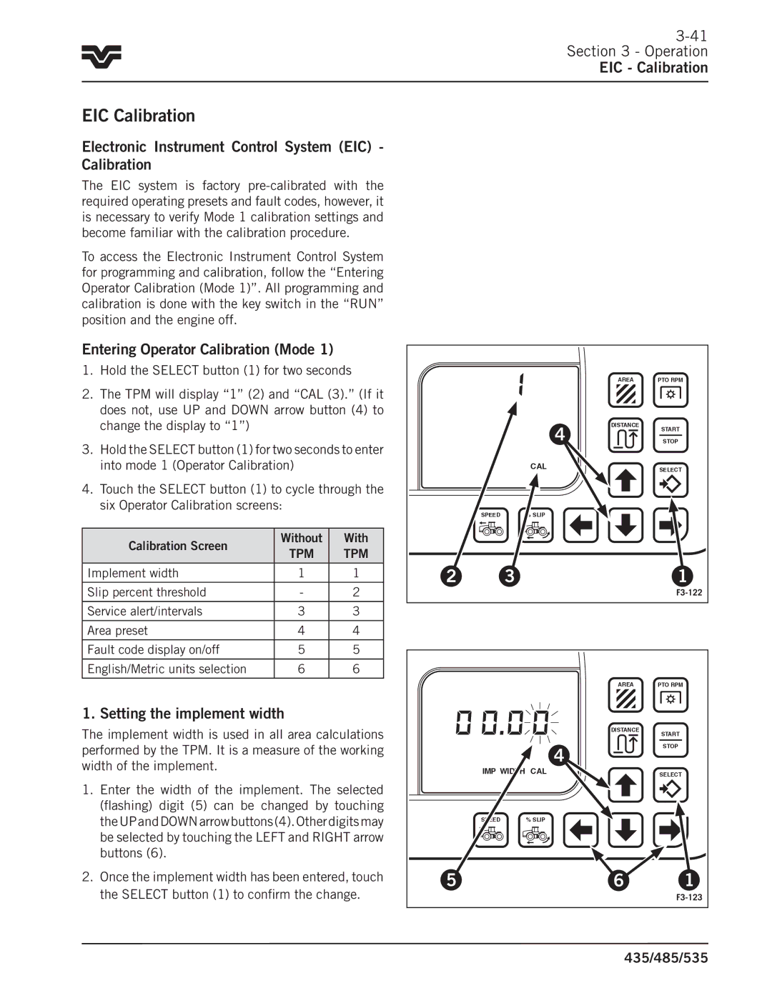
1.Hold the SELECT button (1) for two seconds
2.The TPM will display “1” (2) and “CAL (3)..” (If it does not, use UP and DOWN arrow button (4) to change the display to “1”)
3.Hold the SELECT button (1) for two seconds to enter into mode 1 (Operator Calibration)
4.Touch the SELECT button (1) to cycle through the six Operator Calibration screens:
Calibration Screen | Without | With | |
TPM | TPM | ||
| |||
|
|
| |
Implement width | 1 | 1 | |
|
|
| |
Slip percent threshold | - | 2 | |
|
|
| |
Service alert/intervals | 3 | 3 | |
|
|
| |
Area preset | 4 | 4 | |
Fault code display on/off | 5 | 5 | |
|
|
| |
English/Metric units selection | 6 | 6 | |
|
|
|
1. Setting the implement width
The implement width is used in all area calculations performed by the TPM.. It is a measure of the working width of the implement..
1.Enter the width of the implement.. The selected (flashing) digit (5) can be changed by touching theUPandDOWNarrowbuttons(4)..Otherdigitsmay be selected by touching the LEFT and RIGHT arrow buttons (6)..
2.Once the implement width has been entered, touch the SELECT button (1) to confirm the change..
|
| AREA | PTO RPM |
| 4 | DISTANCE | START |
|
| ||
|
| STOP | |
| CAL |
| SELECT |
SPEED | % SLIP |
|
|
2 | 3 |
| 1 |
|
|
| |
|
| AREA | PTO RPM |
|
| DISTANCE | START |
|
|
| |
| 4 |
| STOP |
|
|
|
IMP WIDTH CAL |
| SELECT |
SPEED % SLIP |
|
|
5 | 6 | 1 |